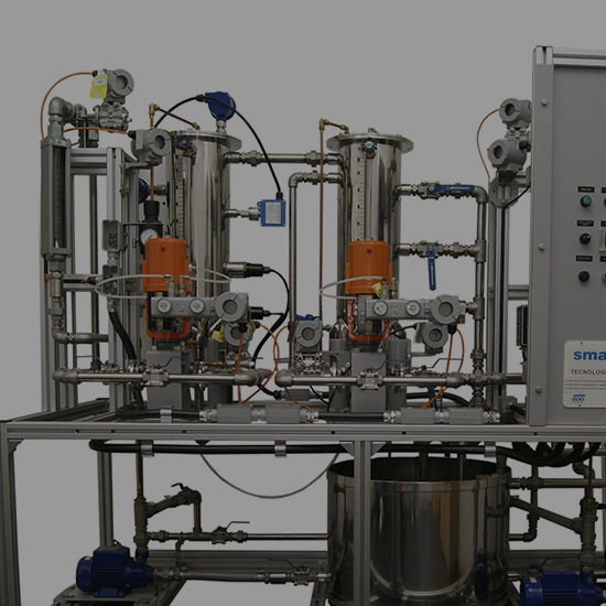


Soluções em
Automação para Indústrias
Automação para Indústrias
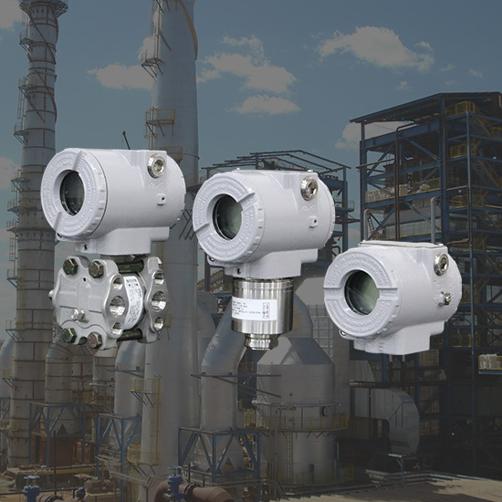
Solução com os melhores recursos tecnológicos em instrumentação e controle, garantindo um melhor desempenho do processo e de um produto final com qualidade.
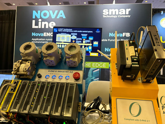
Linha NOVATecnologia O-PAS
Sistema de controle distribuído que implementa a tecnologia O-PAS, Open Process Automation Standard. A ferramenta de configuração NovaCSB é o elemento principal do sistema.
Soluções em
Tecnologias e Softwares
Tecnologias e Softwares
Soluções em softwares, hardwares e tecnologias, pronto para transformar o desempenho do seu setor.
Eventos
e-TECHN
Março 21, 2024 - Recife-PE
Ver mais
OTC
Maio 06-09, 2024 - HOUSTON-TEXAS-USA
Ver mais
BAHIA OIL & GAS ENERGY
Maio 22-24, 2024 - Salvador-BA
Ver mais
e-TECHN
Junho 6, 2024 - Contagem-MG
Ver mais
UDOP
Julho 02-03, 2024 - Araçatuba-SP
Ver mais
FERSUCRO - STAB
Julho 10-12, 2024 - Maceió-AL
Ver mais
Visão Agro - Centro Sul
Julho 16, 2024 - Piracicaba-SP
Ver mais
FENASUCRO
Agosto 13-16, 2024 - Sertãozinho-SP
Ver mais
Vision Tech Summit
Outubro 09-10, 2024 - Ribeirão Preto-SP
Ver mais
AUTOMA
Outubro 14-15, 2024 - Alemanha
Ver mais
FENASAN
Outubro 22-24, 2024 - São Paulo-SP
Ver mais
MEORGA Bochum
30 de Outubro de 2024
Ver mais
Visão Agro
Dezembro 05, 2024 - Ribeirão Preto-SP
Ver maisNotícias