
Hall Sensor The technology of latest-generation Intelligent Positioners

INTRODUCTION
The advancement of Physics and Electronics has been remarkable in the last few years, both being undoubtedly those that developed the most. In current days it seems impossible to live without the facilities and benefits provided by these areas to our daily routines. In industrial process and control we also witness the progress with the outcome of microprocessors, the Fieldbus technology, the Internet, etc.
In this article we will describe an interesting application of Physics in the development of the Sensor Hall-based Smart Valve Positioners combining multiple resources of performance and diagnostics.
HALL SENSOR
The name Hall Sensor derives from the Hall effect discovered in 1879 by Edwin Hall.
This effect results from the Lorentz force on the movement of electrons subject to a magnetic field.
When there is a current flow on a material that is not exposed to a magnetic field, the equipotential lines crossing this flow are straight lines.
The Lorentz force on the electron movement is given by:
F = q x (v x B)
where:
- q: electron load
- B: magnetic field
The external product indicates that the force has mutually perpendicular direction to the current flow and the magnetic field.
When there is a current flow in a material under the influence of a perpendicular magnetic field, the angle through which the current flow is changed by the magnetic field is known as Hall angle. It is a parameter dependent on the type of material and it is determined by the mobility of the electron m that also determines the coefficient of Hall RH. In this case, the equipotential lines along the length of the material are inclined and this shows the Hall tension measured. In other words, the tension is proportional to the magnetic field applied.
The effect Hall is present in all materials, but it is only applied efficiently where the mobility of the electron is relatively high, as in gallium arsenate (GaAs).
In a constructive sense, consider summarily a given material (figure 1) with width d, conducing a current i along its length and subject to a magnetic field B applied perpendicularly to the direction of its width. The result is the generation of tension known as the Hall tension, VHALL, whose magnitude is given by:
VHALL = (RH/d) x i x B where RH is the material constant Hall.
.jpg)
Figure 1 – HALL sensor principle of construction and work
Currently, there are several applications for these sensors, from the application in servo-motors in video cassettes, access control turnstile sensors, speed sensors, automobile motor injection system, current, power and magnetic field measurement, control of brushless DC motors, proximity sensors, rotation control, position control, etc. This last application will be described when dealing on Valve/Actuators Intelligent Positioners. It is about electronics and software intelligence combined with the state of art in mechanical development.
THE INTELLIGENT POSITIONER
This type of equipment is extremely important in any industrial area, working as the final coupled control element to actuators and valves. It must meet several operational requirements easily achieved with the Hall sensor technology, such as:
- High sensitivity;
- High temperature resistance;
- Negligible linearity errors;
- Negligible vibration errors;
- Repeatability and stability, minimizing consumption and reducing process variability;
- High reliability, ensuring operational continuity and safety;
- Versatility, flexibility of use regardless of maker and type of valve/actuator, as well as the course of movement, which facilitates adequacy to new demands;
- Easy to operate with minimum adjustments, which simplifies the installation, operation and maintenance, reducing operation downtime;
- Provides advanced diagnosis functions, operational and maintenance costs, time saving and process improvement, thereby guaranteeing the continuous improvement of processes.
The conventional technology for actuation equipment is based on mechanical couplings, with complicated, low sensitivity and precision mounting and adjustments, most times responsible the process variability that reflects on the stability of controls, the quality, etc.
The last generation of intelligent positioners for valves of simple action linear control (coil return) or double action like globes, boxes, diaphragms, etc, rotary control valves like spheres, butterflies or plugged with pneumatic actuators as diaphragms, pistons etc, is based on piezo-blade (?), one that has been the market choice for field use and on the Hall effect position sensor, without physical contact, for high performance and safe operation.
- Compact and modular project
- Low air consumption
- Easy to install
- Position Sensor without mechanical contact
- Works with simple or double action linear and rotary actuators
- Easy to adjust and remote parameterization via Foundation Fieldbus, Profibus PA or local adjustment with display
- Flow via software feature
- Self diagnosis
.jpg)
Figure 2 – Intelligent Positioner with Hall sensor technology, without mechanical contact
The output module main parts are: pilot, servo, Hall effect sensor and output control circuit.
The control circuit is based on a widely used and well-accepted technology: the piezo blade and spool valve.
A piezo-electric disk is used as blade on the pilot stage. The blade is deflected when it receives a tension through the control circuit. The small air flow that circulates by the beak is blocked altering the pilot chamber pressure, which is called pilot pressure.
The pilot pressure is very low, without flow capacity and must be amplified on the servo section. The servo section has a diaphragm on the pilot chamber and a smaller diaphragm on the spool chamber. The pilot pressure is applied on the pilot chamber diaphragm, which, on an equilibrium state, will match the force applied by the spool valve on the spool chamber smaller diaphragm.
Therefore, when the position is altered via positioner, the pilot pressure increases or decreases as explained on the pilot stage and this change on the pilot pressure forces the valve upward or downward, altering the output 1 and output 2 pressures until reaching a new balance, which results on a new valve position.
.jpg)
Figure 3 – Pneumatic Transducer Scheme
.jpg)
Figure 4 – FY300
The Hall sensor is located and protected internally in the transducer module. The magnet is attached to the valve or the actuator axis, as shown on figure 4 (for teaching purposes), whose result will be the application of the magnetic flow to the Hall sensor and the characterization of the position, which takes into account the center of the magnets, where the field is null.
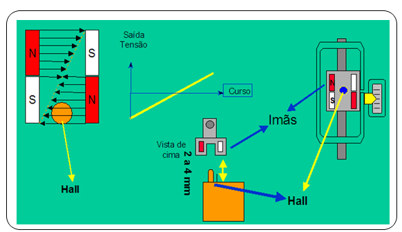
Figure 5 – Hall Sensor work scheme on the Valve Positioner
So, the only detail on the mechanical mounting is to check if the arrow engraved on the magnet coincides with the arrow engraved on the positioner when the valve reaches half of its course.
Therefore, when the valve reaches half of its course, the Hall sensor will receive null field and the CPU will know internally that this corresponds to 50% of its course. One extreme of the course will have, for example, maximum voltage signal of 100%, and the other extreme will have minimum signal of 0%. The voltage on the extremes will be measured during the self calibration process, whose positioner determines without the user intervention the Hall voltages equivalents to the physical limits of the course in a precise and safe way.
Figure 6 shows the positioner functional diagram for the Profibus PA protocol:
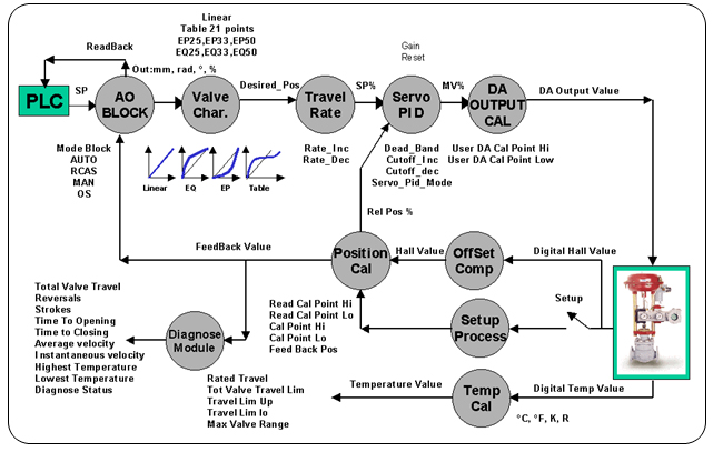
Figure 6 – Smar FY303 Positioner functional diagram
This diagram shows that the positioner receives via PLC (Class 1 master) the set point required by the control strategy. Depending on the operation mode, if automatic or cascade, this set point will be written via cyclic services on the SetPoint or Rcasin parameters of the AO block, respectively. This value will be analyzed by the block algorithm for the alarm and fail safe conditions to characterize this value according to the valve or the actuator curve, by choosing from Linear, 21-point table, EQ25, EQ33, EQ50, EP25, EP33 and EP50. These curves allow for small set point variations to bring the final element near to 100% (EP). Once the transference curve is defined with this set point, so are defined the %/s variation rates on the final element. The servo PID then receives this signal plus the real position via Hall sensor signal, which is characterized during the self-calibration process or even during an user calibration, often used on split-range applications. The VM% signal is then calculated and will generate the converter D/A value that will act on a Piezo sensor and build the pressure on the positioner chamber when it reaches the equilibrium point according to the set point issued by the master. The AO block will restore its real position and will close the loop with the master via parameter ReadBack.
Diagnosis functions can be monitored via Hall sensor signal and class-2 master, such as:
- Odometer, through which the valve course can be predicted statistically during maintenance;
- Strokes, where the valve seats wear can be verified on the extreme conditions of its course physical course;
- Reversals, to watch how frequently there was the set point inversion and analyze the loop tuning. An excessively high number of reversals mean that the tuning is not good and the process variability may be harmed;
- Medium and instantaneous displacement speed, in addition to opening and shutting times for identification of possible jamming and mechanical stress or air leak problems;
- The highest and lowest temperature the positioner was subject. In cases that the temperature is a limiting factor, the FY303 can be used with a remote Hall sensor or even on difficult access locations or those subject to vibration, at distances up to 20m. See figure 7. This is a Hall sensor characteristics:
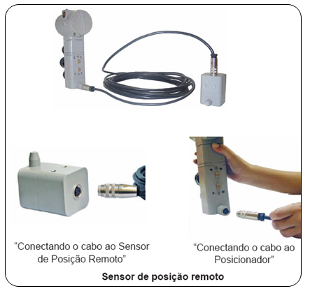
Figure 7 – Remote Hall positioner
Smar also supplies the FY303 with pressure sensors, whose diagnosis functions integrate the equipment.
The FY303 still provides environment temperature signal as secondary feature.
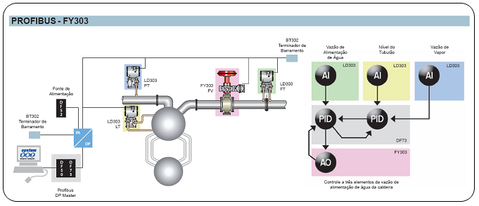
Figure 8 – Example of application in Profibus
Partial Stroke Test or PST
Tests and maneuver involve costs related to plant shutdown and acquiring additional equipment for the execution of valves, actuators and positioners tests.
Usually the additional equipment is made up by manual blocking valves, deflection piping, solenoid valves, course-end mechanical devices and, last but not least, logistics, the number of professionals involved in the activity and possible loss of earnings.
The ideal would be more frequent and well scheduled tests. Also, parameters that indicated the valve level of decay and allow preventive maintenance practices, before the emergency occurred. And that the costs involved were much smaller.
A simple, cheaper and more reliable solution is to adopt the PST – Partial Stroke Test. The PST is simply moving the valve partially and measure the effort applied on that movement. The advantage: the valve speed response can be measured too. Or even check if the valve is not jammed or if the pneumatic actuator is adequately pressurized, without having to go where it is installed.
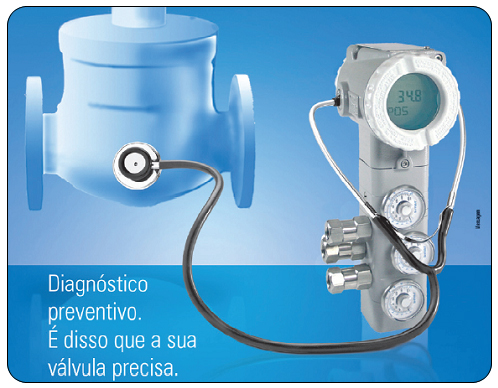
Figure 9 – Preventive Diagnostics
Preventive diagnostics.This is what your valve needs.
However, the automatic PST at acceptable costs only came true with the development of the Intelligent Valve Positioner and the wide range of parameters available that generate an excellent spectrum of diagnostics.
The newest family of SMAR Intelligent Valve Positioners, the FY400, already includes the PST as a factory- supplied firmware, at no additional cost, with the commands for user configuration.
Furthermore, the FY400 was developed in EDDL (Electronic Device Description Language) compliant to the FDT Group (Field Tool Device) Standards. The Device Type Manager (DTM) drivers for configuration and visualization in computer stations with the FDT application are available at the Smar site for download at no cost.
As a consequence from the excellent PST results for the FY400, Smar has just expanded this feature to the FY303 for Intelligent Valve Positioners with the Profibus communication protocol. At no extra cost. And by the same token the DTMs were developed for the FY303, also available free at the Smar page on the Internet.
There follows some examples of DTM screens that illustrate PST features incorporated to the FY303.
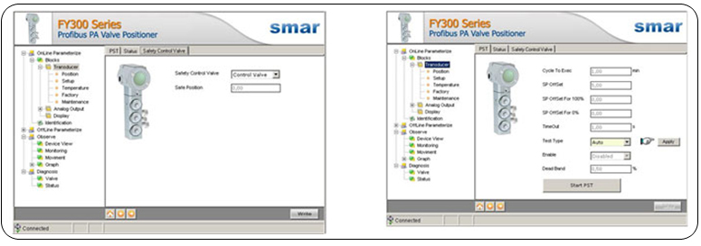
Figure 10 – Examples of DTM screens for the FY303
Through the DTM screens it is possible to configure not only the partial course, but also the periodicity that the PST is executed automatically, namely, without interference from the operator or instrumentation technician. The Smar Intelligent Valve Positioner PST can be executed in intervals varying from 4 minutes through one year (8760 h).
In addition, the PST is feasible from the SMAR asset management device, the AssetView. The data resulting from the test can be easily visualized on the AssetView different presentation and monitoring screens.
The method used by the FY303 and FY400 to execute the PST is known as Dynamic Ramp method. The positioner generates automatically a variation on the ramp of the Set Point signal on the band determined by the user (Off Set). The valve move in response to the Set Point variation, while the positioner measures the valve position through the position sensor without mechanical contact, based on the Hall Effect. At the same time, the positioner measures the pressure applied necessary to move the valve shaft. After reaching the maximum Off Set point, the positioner reverses the ramp so that the valve returns to its original position. Likewise, during the reversion the positioner measures the valve position and the respective activation pressure. At the end of the test, the FY calculates and provides the valve load factor, i.e. the pressure value required to move the shaft and also the graph resulting from the test.
The figures below show examples of the PST result on the FY303 and FY400 according to the FDT/DTM protocol. Similar screens are available also in SMAR AssetView.
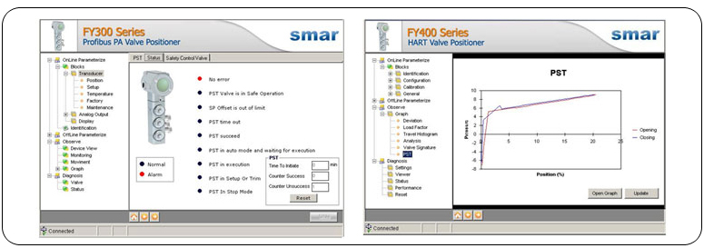
Figure 11 – PST results screens
When considering the growing interest for Safety Instrumented Systems – SIS, the PST is already recognized and influences the calculations relative to the Probability of Failure on Demand – PFD used to determine the Safety Integrity Level – SIL.
CONFIGURATION AND PARAMETERIZATION OF THE FY303 INTELLIGENT POSITIONER - PROFIBUS-PA
Configuring acyclically the FY303
These devices can be configured locally with the magnetic tool, without opening its cover, or remotely through the SMAR ProfibusView or the Siemens Simatic PDM.
The FY303 was designed to use the PROFIBUS PA protocol and can be configured with any tool working with DD/EDDL, and also the FDT concept (Field Device Tool) and DTM (Device Type Manager), such as the Smar AssetView, FieldCareTM and PACTwareTM. It may also be configured cyclically by any PROFIBUS systems using the GSD (Generic Station Description) file. The PROFIBUS PA also provides information on quality and diagnostics, improving the plant management and maintenance.
The EDDL (Electronic Device Description Language) and DTM are available at the Smar Internet site: https://www.smar.com/en
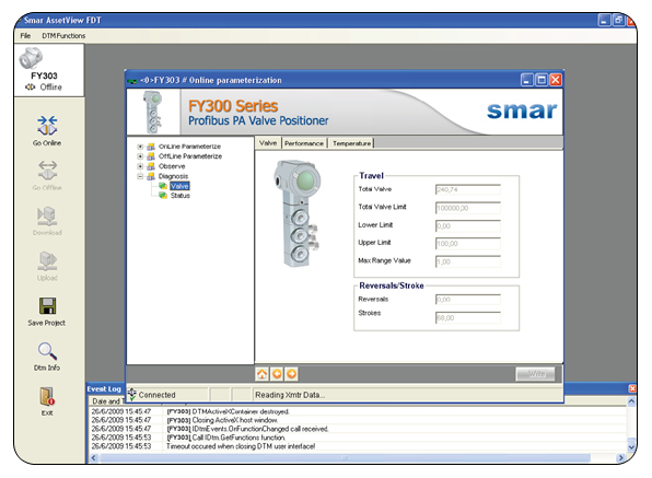
Figure 12 – FY303 - AssetView FTD/DTM
Configuring Cyclically the FY303
Through the GSD file the master executes the entire initializing process with the equipment and provides details for hardware and software revision, equipment bus timing and information on the exchange of cyclic data. The FY303 has an AO functional block with which the master will execute cyclic services and the user must choose the configuration, according to the application. If the AO block is in AUTO, the equipment will receive the set point value and status from the class 1 master, and the user may use this value to write via class2 master. In this case, the set point status must always be equal to 0x80 (good) and chosen from the following configurations:
- SP
- SP/CKECKBACK
- SP/READBACK/POSD
- SP/READBACK/POSD/CKECKBACK
If the AO block is in RCAS, the equipment will get the set point value and status only via class 1 master and the status will always be equal to 0xc4 (“IA”). The following configurations may be used:
- SP
- SP/CKECKBACK
- SP/READBACK/POSD
- SP/READBACK/POSD/ CKECKBACK
- RCASIN/RCASOUT
- RCASIN/RCASOUT/ CKECKBACK
- SP/READBACK/RCASIN/RCASOUT/POSD/CHECKBACK
Next, see a typical example with the steps necessary to integrate a FY303 equipment to the PA system:
- Copy the FY303 gsd file on the research directory of the PROFIBUS configurator, normally known as GSD.
- Copy the FY303 bitmap file on the research directory of the PROFIBUS configurator, normally known as BMP.
- Once the master is chosen, select the communication rate and remember that when there are couplers, the following rates may be available: 45.45 kbits/s(Siemens), 93.75 kbits/s(P+F) and 12Mbits/s (P+F, SK3). When there is the link device, there may be up to 12Mbits/s.
- ·Add the FY303 with its address specified on the bus.
- Choose the cyclic configuration via parameterization with the GSD file according to the application. Remember that this choice must be compatible with the AO block operation mode. In these conditions, verify the value of the status of the set point value, which must be 0x80 (Good), when on AUTO mode and 0XC4 (IA) when on Rcas.
- The watchdog condition may also be activated, when, after identifying the loss of communication between the slave and the master, the equipment may reach a fail-safe condition. Since the FY303 will be on a final element it is advisable the configuration of a fail-safe value.
For more details, consult the FY303 manual at: https://www.smar.com.br/public/img/produtos/arquivos/fy303me.pdf
CONCLUSION
This article showed the gain in technology and benefits provided by a positioner based on Hall Sensor digital technology, mainly for the ease in mounting and operation. Always remember that this equipment will be always integrated to final elements, critical control points, whose operation requires safety and precision. Flexibility, resourcefulness and generation of diagnostics facilitate the conditions for preventive, predictive and proactive maintenance.
For more details on positioners, consult: https://www.smar.com.br/public/img/produtos/arquivos/fy300ce.pdf
For more details on ProfibusView, Profibus-PA configuration and parametrization tool consult: https://www.smar.com.br/public/img/produtos/arquivos/prviewpame.pdf
For more details on the AssetView maintenance and diagnostics tool consult For more details on ProfibusView, Profibus-PA configuration and parametrization tool: https://www.smar.com/en/product/assetview-online-plant-asset-management-system
REFERENCES
- Profibus Training Material – César Cassiolato
- CASSIOLATO, César, Hall Sensor – The technology of last-generation Intelligent Positioners, Controle & Instrumentação Magazine, Edição nº 81 , Junho de 2003
- https://www.smar.com/en/category/valve-positioners
Reliable Solutions

