
How to determine the equipment necessary for a PROFIBUS-PA network

Introduction
Although very simple, the physical medium technology used on the PROFIBUS-PA, the so-called H1, compliant to IEC61158-2, some projects still keep some details that could be avoided in the field, thereby reducing commissioning and startup time and eliminating undesirable intermittence and shutdown conditions during the operation.
Further on we will elaborate on the physical medium. Follow up the upcoming editions.
Whenever possible, consult the EN50170 and the IEC61158-2 standards for physical regulations, as well as the safety practices for each area.
Measurements require safety actions, to avoid contact with terminals and wiring, as high voltage may occur and cause electrical shock. Keep in mind that each plant and system has its own safety details. Learn about these details before beginning to work!
To minimize the risk of potential problems related to safety, safety regulations and hazardous areas must be respected concerning equipment installation and operation. These standards vary from area to area and are constantly updated. It is the user responsibility to determine which one to follow in his applications and guarantee that the equipament being installed complies with it.
An improper installation or the inadequate use of equipament on applications may harm the performance of a system and the entire process, as well as representing a source of danger and accidents. Therefore, it is recommended using only trained and qualified personnel for installation, operation and maintenance.
Typical PROFIBUS network architecture
Watch figure 1, where the architecture is typically PROFIBUS oriented. On it we can verify the wide physical medium coverage, several topologies and application levels. On this article we will comment some details on the PROFIBUS-PA.
.jpg)
Figure 1 – Typical PROFIBUS network architecture
Network Technologies:
- redundant
- ring
- in line
- star
- Eex / Non-Eex
PROFIBUS-PA
The PROFIBUS-PA is the PROFIBUS solution that meets the requirements for process automation by connecting automation and process control systems with field equipament process control, such as pressure and temperature transmitters, converters, positioners, etc. It can be used as a substitute for the 4 to 20 mA standard.
This technology offers many potential advantages, summarized in functional advantages like the transmission of reliable information, treatment of variable status, safety system in case of failures, equipament with auto-diagnostics capability, equipament rangeability, high resolution in measurements, high-speed discrete control integration, applications in any segment, etc. Add to that the economic benefits related to installations (reduction up to 40% if compared to conventional systems, in some cases), reduction of maintenance costs up to 25% in relation to conventional systems, less startup time and a significant increase in functionality and safety.
PROFIBUS-PA permits measurement and control through a line of two single wires. It also allows powering field equipament in intrinsically-safe areas, in addition to maintenance and connection/disconnection of equipament with on-going operation without interfering with other stations in potentially explosive areas. The PROFIBUS-PA was developed in cooperation with the users of NAMUR, the Control and Process Industry, and complies with the application area special requirements:
- The original application profile for process automation and interoperability of field equipament different makers.
- Addition and removal of bus stations even in intrinsically safe areas, without influencing other stations.
- A transparent communication between the PROFIBUS-PA automation bus and the PROFIBUS-DP industrial automation bus through segment couplers.
- Supply and data transmission through the same pair of wired based on the IEC 61158-2 technology.
- Use in potentially explosive areas with ‘intrinsically safe’ or ‘without intrinsic safety’ types shield.
Its synchronous transmission compliant to the IEC 61158-2 standard with a transmission rate defined in 31,25 Kbits/s meets the chemical and petrochemical industries requirements. It provides power supply through the bus, in addition to intrinsic safety. Therefore, the PROFIBUS can be used in hazardous areas, and its options and limitations regarding the IEC 61158-2 standard transmission technology are defined by the FISCO -Fieldbus Intrinsically Safe Concept model. The FISCO model was developed by the German PTB (Physikalisch Technische Bundesanstalt) model and nowadays is internationally recognized as the basic model for buses in classified areas.
The transmission, frequently referred to as H1, is based on the following principles:
- each segment has only one power supply source;
- power is not supplied to the bus with a station at work;
- the field devices consume a basic constant current while at rest;
- the field devices act as passive current consumers (sink);
- a passive line termination is required on both ends of the main bus line;
- linear, tree and star topologies are allowed.
In the modulation case, it is supposed that a basic current of at least 10 mA is consumed by each bus device. By energizing the bus, this current powers the field devices. The communication signals are then generated by the device, which sends them to the basic current by a modulation of + /-9.
|
Data transmission |
Digital, bit-synchronized,. Manchester code |
|
Transmission rate |
31,25 Kbits/s, tension mode |
|
Data safety |
Preamble, error-proof start and end limiter |
|
Cables |
Shielded twisted pair |
|
Power supply |
Via bus or external (9-32 Vdc) |
|
Explosion-protection Class |
Intrinsic safety (Eex ia/ib) and wrapping |
|
Topology |
Bus or star/tree, or combined |
|
Number of Stations |
Up to 32 stations per segment, maximum of 126 |
|
Maximum Distance without repeater |
1900 m (Type A cable) |
|
Repeaters |
Up to 4 repeaters |
Table 1 – IEC 61158-2 characteristics
For a PROFIBUS network to be operated in classified areas it is necessary that all the components used in the classified area be approved and certified in compliance with the FISCO and IEC 61158-2 models by authorized certifying bodies such as PTB, BVS (Germany), CEPEL, UL, FM (USA). If all authorized components are certified and if the rules for selecting the power supply source, cable length and terminators are observed, no additional approval will be required for the PROFIBUS network commissioning.
FISCO
- R´:15 ... 150 Ohm/km;
- L´: 0,4 ... 1 mH/km;
- C´: 80 ... 200 nF/km.
- In terms of termination:
Type A Cable: 0,8 mm2 (AWG18)
In terms of termination: :
- R = 90 ... 100 Ohms;
- C = 0 ... 2.2 µF.
The FISCO concept was optimized in order to permit a greater number of field equipment, according to the bus length and considering the variation of the cable characteristics (R', L',C') and terminators to satisfy categories and groups of gases with a simple evaluation of the installation involving intrinsic safety. With this, the capacity of current per segment was increased and the evaluation was facilitated for the user. Furthermore, when acquiring certified products, the user no longer needs to worry about calculations, even for replacement during operation.
.jpg)
Figure 2 – Example of PROFIBUS-PA signal in tension mode.
.jpg)
Figure 3 – Example of Manchester codification
An equipment transmission typically supplies 10 mA to 31.25 kbit/s in an equivalent load of 50 O, creating a modulated voltage signal of 750 mV to 1.0 V peak to peak, although in safety applications (IS) the requirements for safety barriers should comply with the intrinsic safety barriers.
.jpg)
Figure 4 - 31.25 kbit/s Voltage Mode.
The total cable length is the totality of the trunk size (main bus) and all spurs (derivations bigger then 1m), bearing in mind that with the A type cable, the length is a maximum of 1900 m in unsafe areas. In safe areas it is a maximum of 1000 m with the A type cable and the spurs must not exceed 30m
PROFIBUS-PA topologies
Figures 5 and 6 show the main PROFIBUS-PA topologies, although in practice there is a combination of two types, bus and star/tree topologies.
.jpg)
Figure 5 – Tree or Star topology
.jpg)
Figure 6 – Bus topology
Figure 7 shows a SMAR compact and low-cost solution with one PROFIBUS-DPB1 master and 4 DF97 channels on the same controller with an up-to-12 Mbits/s rate. SMAR has the DF95 model for 2 PROFIBUS-PA channels.
DF97 – Master Profibus-DPV1 with 4 Profibus PA channels
Up-to-32 PA equipment
.jpg)
Figure 7 – DF97 – SMAR Profibus DPV1 master with 4 PROFIBUS-PA channels and 1 PROFIBUS-DP channel.
Basically, the following elements are included in a PROFIBUS network:
- Masters: are the elements responsible for the bus control. They have two classes:
- Class 1: responsible for cyclical operation (reading/writing) and control of open and closed loops on the control/automation system (PLC, controllers, CPUs).
- Class 2: responsible for the PA equipment access of acyclic parameters and functions, engineering station or operation station: ProfibusView, AssetView, Simatic PDM, Pactware, etc.
- DP/PA couplers: devices used to translate the physical characteristics between the PROFIBUS DP (Rs485) and the PROFIBUS PA (H1:31,25 kbits/s). And still:
- They are transparent for masters (do not have physical bus address);
- Meet Ex and Non-Ex applications by defining and limiting the maximum number of equipment in each PROFIBUS PA segment. This number depends among other factors on the totality of quiescent currents and the equipment failures (FDE) and on the wiring lengths;
- Can be powered up to 24 Vdc, depending on the maker and the classification area;
Can work with the following communication rates, depending on the maker: P+F (93.75 kbits/s and SK3:12Mbits/s) and Siemens (45.45 kbits/s).
.jpg)
Table 2 – DP/PA Coupler Data (for more details consult the manufacturer).
.jpg)
Table 3 - DP/PA Coupler Data P+F (for more details consult the manufacturer).
- Link devices: Are the devices used as slaves on the PROFIBUS DP network and as masters on the PROFIBUS PA network. They get high speeds up to 12Mbits/s on the DP bus and also:
- Have physical bus address ;
- Allow the connection of up to 5 DP/PA couplers, but to 30 the equipment on a “Non-Ex” bus and to 10 “Ex” buses. According to the amount of data exchanges cyclically, they accept a maximum 64 equipment.
- PA network bus terminator: consists of a1µF capacitor and one 100 O resistor connected in series between them and in parallel to bus. Their functions are:
- Current signal shunt: the communication signal is transmitted as current but is received as voltage. The conversion is provided by the terminator.
- Protection against communication signal reflection: it must be installed on both bus ends, at the end and generally at the DP/PA coupler.
Some details in terms of project and number of equipment per PROFIBUS-PA segment
Check the number of equipment (N) per PROFIBUS-PA segment, bearing in mind that it is the function of the quiescent consumption of each PROFIBUS PA equipment, the distances involved (loop resistance of A type cable: 44 O/km); the DP/PA coupler and its drained current, the area classification (Classified area couplers drain current around 100 ma, voltage output of 12 V), besides FDE current. The total segment current must be less than the one drained by the coupler.

Where:
.jpg) = PROFIBUS-PA segment current
= PROFIBUS-PA segment current
.jpg) = totality of quiescent currents of all the equipment on the PROFIBUS-PA segment
= totality of quiescent currents of all the equipment on the PROFIBUS-PA segment
.jpg) = additional current, normally negligible in case of failure
= additional current, normally negligible in case of failure
.jpg) = free current, useful in case of expansion or change of manufacturer
= free current, useful in case of expansion or change of manufacturer
.jpg) = current drained by the DP/PA coupler
= current drained by the DP/PA coupler
In addition, there must be at least 9.0 V on the terminal block of the PROFIBUS-PA equipment most distant from the DP/PA equipment:

 > 9.0 V : this will ensure the supply of power to the last PROFIBUS-PA equipment ( in practice, the formula >= 10.5V is adopted to ensure a free current). It is worth remembering that the communication signal must have an excursion of 750 to 1000 mV.
Where:
.jpg) = DP/PA coupler output voltage
= DP/PA coupler output voltage
R = Loop Resistance (Cable type A R = 44 O/km)
L = PROFIBUS-PA bus total length
 = Terminal block voltage of the PROFIBUS-PA most distant from the DP/PA coupler
Some junction boxes or short circuit segment protectors, also known as spur guards, can be powered via PA (H1) bus, so it must be included the current total calculation. Furthermore, each spur guard output has an allowed limit that must be observed.
Calculation of the equipment on a non-Ex PROFIBUS-PA segment
Next will be shown the calculation on a maximum length of 1900 m (for A-type cable), considering the following data:
- Minimum voltage for a PROFIBUS-PA equipment to operate: 9 Vdc
- Typical voltage supplied by a Non-Ex DP/PA coupler: 19Vdc
- Typical current supplied by a Non-Ex coupler: 400 mA
- A-type cable loop resistance (AWG 18): two-way 44 Ohms/Km
- We will neglect the currents of SMAR PROFIBUS-PA FDE Equipment that consume 12 mA.
Taking the Ohm law for basis:
V = RxIx(N)
N = V/(IxR), where
V = maximum cable voltage drop ensuring the power supply for the most distant equipment from the DP/PA coupler.
I = current of each PROFIBUS-PA equipment
R = total resistance
N = total equipment
By replacing the values:
N = (19-9)/(12x10-3 x 1.9x 44) = 10 equipment
Checking the total current against the maximum current supplied by the DP/PA coupler, the result is:
I = 10 x 12mA = 120mA < 400mA .jpg) OK
OK
Now let us admit an A-type cable and a length of 1400 m:
N = (19-9)/( 12x10-3 x 1.4 x 44) = 13 equipment
Checking the total current against the maximum current supplied by the DP/PA coupler, the result is:
I = 13 x 12 mA = 156mA < 400mA OK
Calculation of the A-type cable length for 20 equipment on a non-Ex PROFIBUS-PA segment
L = (19-9) x 1000/(20 x 12x10-3 x 44) = 947 m
By checking the total current with the maximum current supplied by the DP/PA coupler, the result is:
I = 20 x 12mA = 240mA < 400mA OK
Calculation of the total equipment on a Eex ia IIC PROFIBUS-PA segment
Below we will show the calculation on a maximum length of 1000 m (A-type cable, Ex area), considering the following data:
- Minimum voltage for a PROFIBUS-PA equipment to operate: 9 Vdc
- Typical voltage supplied by an Ex DP/PA coupler: 12.5 mA
- Loop resistance of the A-type cable (AWG 18): 44Ohm/Km (two way)
- We will skip the FDE currents
- SMAR PROFIBUS-PA equipment consume 12 mA
Taking the Ohm law for reference:
- N = V/(IxR), where:
- V = maximum cable voltage drop ensuring the minimum voltage supply for the most distant equipment from the DP/PA coupler.
- I = total current of the PROFIBUS-PA segment
- R = total resistance
- N = total equipment
By replacing the values:
N = (12.5-9)/( 12x10-3 x 1.0x 44) = 6 equipment
By checking the total current with the maximum current supplied by the DP/PA coupler, the result is:
I = 6 x 12mA = 72mA < 100mA .jpg) OK
OK
Calculation of the A-type cable length for 8 equipment on a Eex ia IIC PROFIBUS-PA segment
By checking the total current with the maximum current supplied by the DP/PA coupler, the result is:
I = 8 x 12mA = 96mA < 100mA .jpg) OK
OK
By determining the length:
L = (12.5-9) x1000/(8x12x10-3 x44) = 828.6 m
Note that the total equipment is entirely dependant on the area classification, the cable type, the current and voltage supplied by the DP/PA coupler and the total quiescent current of the PA equipment.
It is common practice to consider a voltage of at least 10.5V on the calculation for the most distant DP/PA coupler (9.0 V on the examples), to ensure the integrity of the signal levels. On the above calculations, for simplification the currents for a segment expansion were not included, nor even when replacing the most consuming equipment. In practice, it is advisable to be always alert to these details.
Total PROFIBUS-PA cable length
The PROFIBUS-PA cable length must be totalized from the output of DP/PA conversion point through the most distant segment point, considering derivations. Remember that spurs smaller than 1 m are not included. The total cable length is the totality of the trunk size (main bus) plus all the spurs (derivations smaller than 1 m), and the A-type cable maximum length on classified areas is 1900 m without repeaters. In classified areas the maximum length is 1000 m, with maximum spur of 30 m.
It is advisable to avoid splicing on the installation and distribution. Splices are any parts on the network with an impedance alteration, possibly caused by a alteration on the cable type, the shield continuity, cable crushing of folding, etc. In networks with total length in excess of 400 m the totality of the length of all splices must not exceed 2% of the total length and must not exceed 8 m on lengths shorter than 400 m.
The maximum PROFIBUS-PA segment length when using different types of cable is limited according to the following formula:
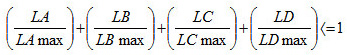
Where:
- LA:Cable A length;
- LB:Cable B length
- LC:Cable C length ;
- LD:Cable D length;
- LA max:Maximum permissible cable A length (1900 m)
- LB max:Maximum permissible cable B length (1200 m)
- LC max:Maximum permissible cable C length (400 m);
- LD max:Maximum permissible cable D length (200 m)
With relation to spurs, it is necessary to be alert with their lengths. The total PA equipment to be considered when there is repeaters must comply with the Table 4. In classified areas the maximum spur is 30 m.
|
Total PA equipment per DP/PA coupler segment |
Spur length (m) with 1 equipment |
Spur length (m) with 1 equipment |
Spur length (m) with 3 equipment |
Spur length (m) with 4 equipment |
Length with maximum number of spurs (m) |
|
1-12 |
120 |
90 |
60 |
30 |
12 x 120 =1440 |
|
13-14 |
90 |
60 |
30 |
1 |
14 x 90 = 1260 |
|
15-18 |
60 |
30 |
1 |
1 |
18 x 60 = 1080 |
|
19-24 |
30 |
1 |
1 |
1 |
24 x 30 = 720 |
|
25-32 |
1 |
1 |
1 |
1 |
1 x 32 = 32 |
Table 4 – Spur x number of PROFIBUS-PA equipment
Note: The cable capacitance limit must be considered when the effect on a spur signal is smaller than 300 m and is similar to a capacitor. When lacking data from the cable manufacturer the value of 0.15 nV/m can be used for PROFIBUS cables.
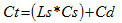
Where:
CT: Total capacitance in nF;
LS: Spur length in m;
Cs: Wire capacitance per segment in nF (standard: 0.15);
Cd: PA equipment capacitance.
The attenuation associated with this capacitance is 0.035 dB/nF. So, the total attenuation is:
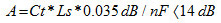
Where 14 dB will allow the minimum necessary signal for existing conditions of identifying it with integrity. See on figure 9 an example of how to calculate the total length of a PROFIBUS-PA segment.
.jpg)
Figure 8 – Example of calculation of the total PROFIBUS-PA network length.
Conclusion
This article presented PROFIBUS-PA details in terms of physical medium, dimensioning and installation that contribute decisively for a PROFIBUS control and automation system to be successful.
The above described does not replace the IEC 61158 e IEC 61784 standards nor PROFIBUS profiles and technical guides. In case of discrepancies or doubts, these rules and the manufacturer manuals prevail. Whenever possible, consult the EN50170 for physical regulations, as well as the safety practices for each area.
References
- SMAR PROFIBUS Manuals
- https://www.smar.com/en
- PROFIBUS training and technical literature - César Cassiolato
- PROFIBUS technical specification and installation guides.
“How to dimension the necessary equipment for a Profibus-PA network”, César Cassiolato, Mecatrônica Atual magazine, edition 48, 2010
Reliable Solutions

