
Industrial Networks - Part 1
Introduction
The demand for automation in the industry and the most different sectors is associated, among many aspects, to the possibility of increasing the speed of the information process, as the operations are increasingly more complex and variable. A greater number of controllers and mechanisms are needed to allow faster decisions and increase the process levels of productivity and efficiency within the premises of operational excellence.
Automation enables energy, work force and raw material savings, better product quality control, more plant availability and operational safety. In essence, industrial automation allows raising the levels of process continuity and global control with more efficiency, bring the closer possible real production figures to the nominal plant capacity by reducing downtime, corrective maintenance and the lack of raw material to the minimum acceptable.
Furthermore, the advent of the automated systems based on field networks and digital technology prompted several benefits in terms of maintenance, and the increase of plant availability and operational safety. And still, automation goes beyond the plant floor towards wider borders: business itself.
.jpg)
Figure 1 – Automation goes beyond plant limits and extends to the finished product, reaching wider borders: business itself.
The complete solution must provide a transparent industrial management methodology to ensure that all the efforts aim at a pre-established goal in favor of decision making when occurring changes of performance relevant to the indicators or a deviation in relation to the original plan.
Users and clients alike should be alert to choose and define a system of automation and control whose definition takes into account several criteria to tune in with the technological progress.
The more the information, the better a plant can be operated and, as a consequence, more products can generate and more profitable it can be. Digital information and truly open systems enable to collect information on the most varied types and objectives of a plant, in an interoperable way, as never seen before. In this sense, the Fieldbus technology (Foundation fieldbus, Profibus, HART, DeviceNet, Asi, etc.) may turn valuable bits and bytes into a profitable relationship and obtain a qualitative gain from the entire automation and control system.
One cannot think only in terms of a field bus, but be aware to the general benefits provided by the system.
The industrial communication revolution on the automation technology is revealing an enormous potential for the optimization of process systems, as well as making an important contribution towards improving the use of resources. Below we will see details of industrial networks that will explain how these networks work as the main connection link of the information flow in automation.
The information technology has been critical for the development of the automation technology, by changing hierarchies and structures on the most diversified industrial environments and sectors, from process and manufacture industries to building and logistic systems. The capability of communication between devices and the use of standardized, open and transparent mechanisms are indispensable components of today´s automation concept. Communication has spread out very fast horizontally on the field level, as well as vertically, by integrating all hierarchy levels. According to the application characteristics and the maximum targeted cost, a gradual combination of different communication systems offers the ideal conditions for open networks in the industrial process.
.jpg)
Figure 2 – Automation pyramid levels
Figure 2 shows that on the actuator/sensor level there are some industrial networks, where the AS-Interface (AS-i) stands out, whose binary signals are transmitted through a very simples and inexpensive bus combined with the power source (24 Vdc) needed to power these sensors and actuators. Another important feature is that the data are transmitted cyclically, extremely fast and efficiently. Later on, we will see more details.
On the field level, the distributed peripherals such as Input/Output (I/O) modules, transducers, drives, valves and operational panels communicate with automation systems via an efficient, real-time communication system (PROFIBUS-DP or PA, Foundation Fieldbus, HART, etc.).The transmission of process data and diagnostics is executed non cyclically, only when necessary.
In relation to cells, the programmable controllers, like CLPs and PCs, communicate with one another, requiring a great number of data packages and powerful communication functions. Furthermore, the efficient integration to the existing corporate communication systems such as Intranet, Internet and Ethernet is absolutely mandatory, and may be carried out by several networks. PROFInet, HSE (High Speed Ethernet), Ethernet IP networks support simple field devices and critical time applications, as well as the integration of automation systems distributed, based in components.
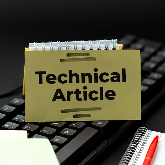
Data Volume Transmission Time Transmission Frequency
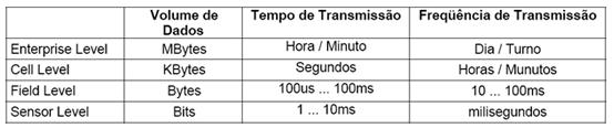
Table 1.1 Requirements for industrial automation communication systems
In the past few years the instrumentation and automation markets have demanded field equipments with high performance, reliability, availability, resourcefulness, etc., such as pressure and temperature transmitters, converters, positioners, actuators and controllers, aiming at minimizing costs, reducing process variability, enabling the reduction of operation and maintenance costs, as well as ensuring the continuous optimization and betterment of the process.
On the other hand, microprocessors and microcontrollers are becoming more powerful and inexpensive, while the instrumentation suppliers are being responsive to the users demand for more and better information on their needs.
Digital technology is rich in providing information, not only pertinent to the process, but primarily to the field equipment. Hence, auto-diagnostic conditions may save operation and maintenance costs, mainly in hazardous areas or even in those hard to reach. From the control room the operator has a general view of the system, with Internet-based tools, any time any place. By managing the information from the field, the right data can be selected for the desired production targets and/or the right people in order to improve the processes.
This technological evolution and the consolidation of industrial networks make the automation and control systems, field equipment, controllers, etc, responsible for functions never imaginable before, as continuous and discrete control, shorter scanning times, redundant architectures, information management and traffic, availability of information for IHMs, Internet, report generation, asset management, high safety levels, etc. All of this, combined with hardware and software reliability.
A little bit of history
The first automation systems were developed in the late XIX century during the industrial revolution. The labor was manual and began being carried out by dedicated and customized machines aiming at improving productivity and efficiency. Control functions were implemented through mechanical devices that automated some critical and repetitive tasks. These devices were developed for each task and had short useful life and high maintenance due to their mechanical nature.
Later on, with the outcome of relays and contactors, the devices were replaced by automatic instruments in assembly lines, which meant a great progress in those days. The relay logic made possible the development of more complex and sophisticated control functions.
After World War II, there was great technological progress and were launched the numerical command machines, the control systems in the process industry, as well as the voltage reference concept for analog instrumentation. Also appeared the first integrated circuits, the CIs, which helped develop a new generation of automation systems. It is worth mentioning that in 1947, William Shockley, John Barden and Walter Brattain invented the transistor, the electronic component widely integrated in the modern processors.
In the early 70s, the first commercial computers began to be used as controllers on heavy automation systems, in spite of their large size, high cost, occupy too much space, being difficult to program and too sensitive to the industrial environment. Their advantage was handling the acquisition and control of several variables.
Still in the 70´s decade there was a large advancement in the automation field.
The Programable Logic Controller (PLC), was developed in response to the demand of the American automotive industry. The CLPis a dedicated computer designed to operate in the industrial environment, where sensors and actuators are connected to input/output cards. The first CLPs had a small set of instructions: normally only logic conditions; they did not have analog inputs and could
only handle discrete control applications. The CLPs substituted the relay control panels and reduced the high power consumption, the difficult maintenance and modification of commands and also the costly wiring alterations.
In present days, due to the industry demand, the CLPs handle both discrete control and analog loops. These systems are usually called Programable Controllers, since they are not limited to logic conditions operations. The current control functions in a plant are generally distributed among a given number of programable controllers that are assembled near to the equipments subject to control. The different controllers are usually connected via local network to a central supervisory computer that manages alarms, recipes and reports.
We entered a phase whose technology and industrial connectivity were proprietary and there was a “marriage” between client and supplier. The SDCSs (Digital Distributed Control System) were introduced in the market.In the 90´s, the world began witnessing enormous progress in the technological area, whose electronic circuits came to offer more efficiency, higher speeds, more functionalities, Bigger MTBFs (Mean Time Between Failures, for more reliability), smaller consumptions, smaller physical space at reduced costs. At the same time, it boosted the developement of more powerful computers, interfaces and peripherals, with high processing capability and memory, while enabling high scale production, at reduced costs, a general advantage, as it prompted the increase of micro-controller, Cis and ASCIs for the entire industry.
What kind of update can a conventional system have in the coming years? How much will it expand? The portfolio of applications offered by suppliers with an open digital system grew greatly in the last few years, including open digital networks, new areas such as asset management, control based on functional blocks, optimization in real time, alarm management and so on.
Today the user must be attentive and always specify that he wants an open automation system with diagnostic capability, more tolerance to failures, function blocks, FFBs (Flexible Blocks), OPC connectivity and with other protocols, in addition to a series of other features that makes it a complete control system and not a mere communication bus with proprietary integrations. The choice by the main industries is based on the process control functions, which allow aggregating information beneficial to decision making and guarantee operational excellence.
Truly Open Systems employ open technologies that integrate perfectly to the hardware and at the same time enable them to connect with hardware and software from other makers. Users are free to choose their components and even built their own system.
The flexibility and the expanding capability of an open and digital architecture allow reconfiguration and expansions to meet the new process conditions without large reinvestments. The modern technologies make possible quick response to the changing market conditions.
It is worth remembering that in regard to operational excellence any industrial segment is under constant pressure to reach that status, aiming at ensuring its competitiveness. Operation excellence
means to optimize and boost processes through teal time data analysis, to facilitate decision making in an intelligent and strategic way at every corporation level. The use of digital technology permits improving processes, enables managing the plant operation more efficiently.
SMAR´s System302 is an example of a Truly Open System: https://www.smar.com/en/system302. Is a system based on state-of-the-art technologies, totally scalable and integrated that provides a single platform of process control and supervision. The System302 offers a complete hardware and software infrastructure required for the optimized process control, either continuous or batch type. Through technology that combines the world´s best if SDCDs and PLCs/SCADA, the System302 is the complete solution in terms of automation and control systems, whose differential is to use technologies with established architecture, which provides digital and open network technology, without the need for a totally proprietary system. Undoubtedly due to the many advantages of
In the global market, the search for technological advantage that allows the user to compete effectively, keep a sustainable, profitable way and reinvest in his own business, the industrial automation became a basic item for this profit. In the industrial sector, the optimization of resources is a must. In fact, the innovation in the process areas is not many, and the responsibility for cost reductions depends on the process control area. Understanding the innovative processes on the automation of digital systems and open networks may help locate ourselves in the current context, to identify the innovation that can add value to the productive chain. Particularly in the past few years, with the digital electronic advancement, new tools have been introduced in the process control and maintenance areas in association with communication systems based on open industrial protocols.
General Classification of Industrial Networks
Figure 3 shows several industrial networks classifications
As regards physical topology *Bus *Ring *Star *Tree
As regards the network model *Origin-destination *Producer-consumer
As regards the data exchange method * Pooling *Cyclic * Change of status
As regards the type of connection *Point to point *Multiple points
As regards the transmission mode *Serial transmission *Asynchronous transmission
As regards the operation mode *Serial transmission *Parallel transmission
As regards the type of commuting *Circuit commuting *Package commuting
.jpg)
Figure 3 – Industrial Networks General Classification
An important point is to differentiate information network, control network and field network.
The information network represents the highest level in an architecture. In large corporations it is only natural choosing a large capacity backbone to interconnect the ERP (Enterprise Resource Planning), Supply Chain (supplies chain management) and EPS (Enterprise Production Systems) systems.
A control network interconnects the level 2 industrial systems or SCADA systems to the level 1 system, represented by CLPs and remote for data acquisition. It is also possible that level 3 equipment, such as PIMS and MES systems are connected to this bus. Currently the most recommended standard is the Ethernet 100 Basis-T.
A network function is to guarantee the connectivity among the many active devices directly to the plant floor, i.e., level 1 devices, be them data acquisition devices, actuators or CLPs.
The field networks are industrial communication systems that use wide variety of physical media, like copper cables, optical or wireless fibers to couple the field devices to a control system or a management system.
.jpg)
Figure 4 – Industrial network scenario
The industrial network concept was introduced to minimize costs and increase the operability of an application to interconnect an application several devices The use of digital networks and protocols foresees significant advancement in the following areas:
- Installation, operation and maintenance costs
- Maintenance proceedings with asset management
- Easy expansion and upgrades
- Control and quality information
- Determinism (Determines with exactness the time needed to transfer information through the many network participants)
- Low cycle times
- Several topologies
- Open standards
- Several level redundancy
- Smaller measuring variability with improvement of exactness
- Multivariable measuring
The option for implementing control systems based in networks requires an evaluation to determine which type of network is best for the final user, who must look for an application platform compatible with most equipments possible.
PROFIBUS
The history of PROFIBUS began with a joint project of the PROFIBUS association and the German government in 1987. In this endeavor, 21 companies and institutions combined their efforts to create a strategic project for fieldbus. Their goal was to stabilize a bitserial field bus that would standardize a field device interface. Therefore, the relevant member companies of ZVEI, the Electric Industry Central Association, agreed to support a mutual interest technical concept for process manufacture and automation.
The first step was the specification of the PROFIBUS FMS (Fieldbus Message Specification) complex communication protocol, devised for communication tasks requirements.
A step further in 1993 was the conclusion of the specification of a simpler and faster communication variant, the PROFIBUS-DP (Decentralized Peripheral). This protocol is now available in three functional versions, DP-V0, DP-V1 e DP-V2.
Based on these two communication protocols, together with the development of several profiles of oriented applications and a number of fast growing devices, PROFIBUS advanced initially in manufacture automation and, since 1995, in process automation with the introduction of PROFIBUS-PA. Today, PROFIBUS is the world´s leading field bus.
PROFIBUS is an open and independent field network standard of suppliers whose interface between them allows a vast number of applications in processes, manufacture and building automation. This standard is guaranteed in compliance with the EN 50170 and EN 50254 standards. Since January 2000, PROFIBUS was firmly established with standard IEC 61158, alongside seven other fieldbuses. The IEC 61158 is divided in seven parts, named 61158-1 a 61158-6, which encompass the OSI model specifications. This version expanded to include the DPV-2. All over the world users can now use for reference an international open protocol standard, whose development sought and still seeks cost reduction, flexibility, reliability, safety, interoperability, orientation towards the future, to suit the most diverse applications and suppliers.
Today are estimated around 30 million nodes installed with PROFIBUS technology and over 1000 plants with PROFIBUS-PA technology. There are 24 regional organizations (RPAs) and 35 Competence Centers specialized in PROFIBUS (PCCs) strategically pinpointed in several countries to offer support to users. In Brazil, there is the only PCC in Latin America, operating in partnership with FIPAI at the Engineering School of São Carlos – USP.
In terms of communication, the programmable controllers, like CLPs and PCs, keep mutual contact and enable the transference of large data packages via many powerful functions. Furthermore, the efficient integration with the existing corporate communication systems such as the Intranet, Internet and Ethernet is absolutely mandatory. This requirement is enabled by the PROFIBUS FMS and PROFINet protocols.
.jpg)
Figure 5 – Example of a Profibus networkd with the Profibus-DP and Profibus-PA variantes
The PROFIBUS architecture is divided in three principal variants:
PROFIBUS DP
The PROFIBUS-DP is the PROFIBUS high speed solution. It was developed especially for communication between automation systems and decentralized equipment. Oriented to control systems whose enhancement are I/O-distributed devices, the PROFIBUS-DP replaces the conventional 4 to 20 mA, HART or 24-Volt transmission systems and uses RS-485 physical medium or optics fiber. It requires less than 2 m to transmit 1 input and output kbyte and is widely utilized critical time control.
Currently, 90% of the applications involving Profibus slaves use PROFIBUS DP. This variant has three versions: DP-V0, DP-V1 e DP-V2. Each version was designed according to the technological progress and the demand for applications throughout time.
(Quadro)
Functionality of the Devices
DPV2: Deterministic cycle time mode Isochrome mode Slave-slave communication (Data) Publisher/Subscriber Clock and Time Stamp Synchronization Upload and Download Redundancy HART on the DP
DPV1: Exchange of acyclic data between masters and slaves Alarm Handling Integration with EDDL and FTD Fail Safe Functional Blocks
DPV0: Exchange of cyclic data between masters and slaves GSD Diagnostics
.jpg)
Figure 6 – Profibus Versions
PROFIBUS-PA
PROFIBUS PA is the solution that meets the process automation requirements, where automation systems and process control systems connect with field equipment such as pressure and temperature transmitters, converters, positioners, etc. It can replace the 4 to 20 mA standard.
There are potential benefits for using this technology, whose functional advantages include the transmission of reliable information, treatment of variable status, fail-safe system, auto-diagnostics equipment, equipment rangeability, measuring high resolution, integration with discrete control in high speeds, applications in any segment, etc. In addition to economical benefits related to the installations (reduction up to 40%, in some cases, in comparison to conventional systems), maintenance costs (reduction up 25% in some cases, against conventional systems) and smaller startup time contribute to a significant increase in functionality and safety.
PROFIBUS PA enables measuring and control through two simple cables line. It also permits powering field equipment in intrinsically safe areas, in addition to maintenance and connection/disconnection of equipment even during the operation, without interfering in other stations of potentially explosive areas. The PROFIBUS PA was developed in cooperation with NAMUR users, the Control and Process Industry, in compliance with the special requirements of the application area, namely:
- The original application profile for process automation and the interoperability of field equipment from different manufacturers.
- Addition and removal of bus stations even in intrinsically safe areas, without influence over other stations.
- Transparent communication through couplers between the PROFIBUS PA automation process bus and the industrial automation PROFIBUS-DP bus.
- Power source and data transmission over the same pair of cables, based on the IEC 61158-2 technology.
- Use in potentially explosive areas reinforced by “intrinsically safe” or “without intrinsically safe” shields.
The connections of transmitters, converters and positioners on a PROFIBUS DP network are made by a DP/PA coupler. The crossed pair of cables is used on each equipment power source and communication for each equipment, which facilitates the installation and results in low hardware costs, less initiation time, problem-free maintenance, low engineering software cost and high operational trust.
The PROFIBUS protocol architecture and philosophy guarantee to each station involved in the exchange of cyclic data sufficient time to execute its communication task within a defined time interval. To that effect, they use the token passage procedure used by bus master stations to communicate between them, and master-slave procedure to communicate with the slave stations. The token message, a special frame for one master passing the right of access to other, must circulate one time for each master within the maximum defined, configurable rotation time. In the PROFIBUS the token passage procedure is used only for communication between masters.
Multi-master Communication, token passage
Several DP masters can access the slaves with reading functions
.jpg)
Figure 7 Multi-master Communication
.jpg)
Figure 8 – Master-Slave Communication
The master-slave procedure enables the master (with the token) that is active to access its slaves through the reading and writing services.
PROFINET
PROFInet is a network standardized by PROFIBUS International compliant to the IEC 61158-5 and IEC 61158-6.It is one of the fourteen industrial Ethernet networks. Basically, there is two types of PROFInet: PROFInet IO and PROFInet CBA. The PROFInet IO is used in real-time applications with no critical time, like the conversion to the PROFIBUS-DP network.
The PROFInet is an comprehensive automation concept that emerged as the result of the trend of automation for reusable and modular machines in plants with distributed intelligence. Its features meet particularities of the automation technology:
- Consistent communication between the several management levels since the field through the corporate levels using the Ethernet;
- Involves a great number of one protocol and open system manufacturers;
- Uses IT standards;
- Integration with PROFIBUS systems without changes.
PROFInet was defined compliant with the Layer ISO/IEC8802-3, and its DataLink Layer, compliant with the TCP/UDP/IP/Ethernet of ISO/IEC8802-3. Its main focus is the application of the concept of objects already in use that were tested in automation technologies software. According to this idea, machines and plants can be divided in technological modules, each one of them with their characteristics, mechanical and electric-electronic features and application software. Each module is then encapsulated according to PROFInet components and can be accessed via universal interfaces, in addition to being interconnected with several applications. The concept of components should be regarded as the idea of reutilizing software units.
In this regard, PROFInet uses COM components (Component Object Model), while its expansion, the DCOM (Distributed Component Object Model) for distributed systems. Therefore, all objects are identical and look alike. This type of distributed automation system enables modular projects and plants that support the reutilization of machine and plant parts. This ensures interoperability and reduced problems. The integration of PROFIBUS segments and PROFInet is done by implementing proxies, thereby guaranteeing to the user maximum protection to investments. Moreover, the Proxy technology allows the integration with other fieldbuses.
.jpg)
Figure 9 – Creation and interconnection of componentes.
.jpg)
Figure 10 – Structure of PROFInet device
.jpg)
Figure 11 – PROFInet migration model
PROFInet has three different operation models, two of them for real time work. See figure 12.
The first model is based on pure TCP/IP architecture, using Ethernet on layers 1 and 2, IP on layer 3 andTCP or UDP on layers 4. This architecture is called Non-teal time (non-RT), because its processing time nears 100 m. The great application on this time of communication is for network configuration or communicating with the Proxies, using the PROFInet CBA. The Proxies are protocol converters (for example, PRFInet to PROFIBUS-DP, or PROFInet to HART, FF, etc), as shown on figure 13.
.jpg)
Figure 12 - PROFInet has three different operation models
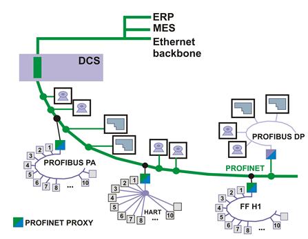
Figura 13 - Proxy PROFInet/PROFIBUS-DP e PROFInet/HART, PROFInet/FF
The second model is based on the Soft Real Time (SRT) whose feature is to be a direct channel between the Ethernet layer and the application. By eliminating several levels of protocol, there is a reduction on the length of the transmitted telegrams, which require shorter time of data transmission on the network. In this case, both PROFInet and CBA types can be used.
The third model is based on the Isochronous Real Time (IRT) concept, for critical response time, shorter than 1 ms. A typical example of this application is for controlling the movement of robots, whose update time must be short. In this case, only the PROFInet IO is used.
Figure 14 – PROFInet CBA and IO providing maximum flexibility to applications
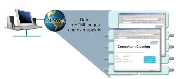
Figura 15 – The access to PROFInet data information can be done through the standard WEB services.
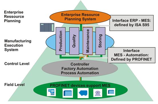
Figure 16 – PROFInet and MES
Foundation Fieldbus
This is a bidirectional, digital communication protocol that enables the network interconnection of several devices directly on the field, and controls and monitors processes and stations (IHMs) through supervisory software. It is based on the ISO/OSI standard, which includes the following layers: Physical Layer, Communication Stack e User Application, whose comprehensive supervision covers Fieldbus Access Sublayer(FAS), Fieldbus Message Specification(FMS) and the Function Blocks model plus Device Descriptions.
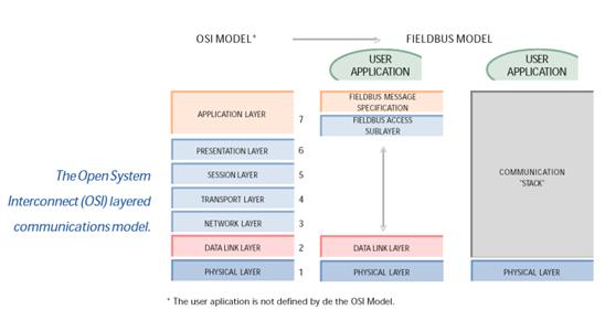
Figure 17 – Structure of Foundation Fieldbus layers
The Physical Layer is defined in compliance with international standards IEC and ISA. It receives messages from the Communication Stack and converts them into physical signals in the fieldbus physical medium and vice-versa, including and removing preambles and limiters of message begin and end.
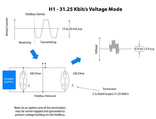
Figure 18 – Example of Fieldbus signal in tension mode
Reliable Solutions

