
PROFIBUS: Grounding Tips, Shielding, Noise, Interference, Reflections, Repeaters and more

|
|
|
.jpg)
Introduction
The coexistence of equipment of different technologies and the inadequacy of the installations favors the emission of electro-magnetic energy and often causes problems of electro-magnetic compatibility.
EMI is the energy that causes undesirable response to any equipment and may be generated by sparking on the motor brushes, tension circuits switching, activation of inductive and resistive loads, activation of switches, circuit breakers, fluorescent bulbs, heaters, automotive ignitions, atmospheric discharges and even the electrostatic discharge between persons and equipment, microwaves devices, mobile communication equipment etc. All this may provoke alterations with the resulting overload, sub-voltage, peaks, voltage transients etc., which may cause high impact on a communication network. This is very common in industries and factories, where EMI is fairly frequent in function of the larger use of machines such as welding instruments, motors (MCCs) and in digital networks and computers in the vicinity of these areas.
The biggest problem caused by EMI is the occasional situations that slowly degrade the equipment and its components. Many different problems may be generated by EMI on electronic equipment as communication failures between devices of the same equipment network and/or computers, alarms produced without explanation, action on relays that do not follow logic, without being commanded, in addition to the burning of electronic components and circuits etc. It is very common the occurrence of noises in power source lines due to bad grounding and shielding or even error in the project.
The topology and the distribution of the wiring, types of cables, proctection techniques are factors that must be considered to minimize the EMI effects. Keep in mind that in high frequencies the cables work as a transmission system with crossed and confused lines, reflect and scatter energy from one circuit to another. Keep the connections in good conditions. Innactive connectors may develop resistance or become RF detectors.
A typical example of how the EMI may affect the work of an electronic component is a capacitor exposed to a voltage peak higher than its specified nominal voltage. This may deteriorate the dielectric, whose width is limited by the capacitor operation voltage, which may produce a gradient of potential inferior to the dielectric rigidity of the material, causing malfunctioning and even the capacitor burning. Or, still, the transistor polarization currents may be altered and cause their saturation or cut, or burn its components by the joule effect, depending on the intensity.
This article will show some details about Profibus, grounding, shielding, noises, interferences, reflections and much more.
In measurements:
- Do not be neglectful, imprudent, irresponsibly inexpert or incompetent on technical problems.
- Remember that each plant and system has its own safety details. Get well nformed about them before starting work.
- Whenever possible refer to the physical regulations, as well as the safety practices for each area.
- Act safely on measurements, avoiding contact between terminals and wiring, as high voltage may cause electric shock.
- In order to minimize the risk of potential problems related to safety, comply with the safety standards and those of the local classified areas regulating the equipment installation and operation. These standards vary according to the area and are being constantly updated. The user is responsible to determine which rules to follow in his applications and guarantee that each device is installed in compliance with them.
- The inadequate installation or use of equipment in non-recommended applications may damage the system performance and consequently the process, as well as be a source of danger and accidents. Therefore, only use trained and qualified professionals on installation, operation and maintenance jobs.
Quite often the reliability of a control system is jeopardized by its poor installations. Commonly, users tolerate them but a close look reveals problems involving cables, their courses and packing, shielding and grounding.
It is extremely important that every person involved is aware and conscious and moreover committed with the plant operational reliability and personal safety.
Reliability of an automation and control system
Many requirements should be followed to ensure the several level of reliability, including:
- Grounding at a single point;
- AC and DC signals free of noises;
- Redundant Sources;
- Redundant controllers;
- Redundant sensors;
- Redundant wiring;
- Etc.
There is a direct relationship between reliability and costs, but, more than this, safety and costs, where, somehow, technical negligence may happen.
NBR 5410
NBR-5410 is the Brazilian standard covering low voltage electrical installations. This regulation guides how to configure and calculate grounding systems, as well as equipotential points to connect electric, electronic and lightning-protection systems.
Complementary regulations:
- NBR 5456 – General Electricity and electronics;
- NBR 5444 –Graphic symbols for electric installations on buildings ;
- NBR 13570 –Electric installations in public areas;
- NBR 13543 – Electric installations in health institutions;
- NBR 5418- Electric equipment installedin potentially hazardous atmospheres;
The concept of grounding
Grounding is the intentional connection of an equipment or system to the ground so that it provides a safe and low resistance path.
Important:
- For indirect contacts there are other means of protection in addition to grounding!
- Do not alter or violate the constructive features of equipment built in compliance with regulations! For example, do not use an equipment previously used on explosion-proof applications in intrinsically safe areas, as the input zener may have been damaged and does not ensure protection according to safety requirements.
Ground wire
Every circuit must have a conductor for protection all through its length.
Grounding in Sensitive Electric Equipment
Grounding systems must execute multiple simultaneous functions: provide personal safety and protect the equipment. To summarize, here is a list of their basic functions:
- Provide users personal safety;
- Provide a course of low impedance return to the ground, while turning off automatically through the protection devices quickly and safely, when correctly designed;
- Control the voltages developed on the ground when the earth-phase short circuit returns through a near or distant source;
- Stabilize the voltage during transient periods on the electric systems due to the lack of grounding;
- Drain static loads accumulated in equipment structures, supports and housings;
- Provide a system that enables the electronic equipment to operate well both in high and in low frequencies;
- Provide a stable voltage reference to signals and circuits;
- Minimize Electromagnetic Emission (EMI) effects.
The neutral conductor is normally insulated and the power source system must be the TN-S (T: directly grounded point; N: masses directly connected to the grounded power source point; S: different conductor for neutral and protection).
The neutral conductor works basically as a means of conducting system return currents.
The protection conductor basically bonds the mass currents to earth. All the housings must be connected to the protection conductor.
The equipotential conductor is the electronic circuit reference potential.
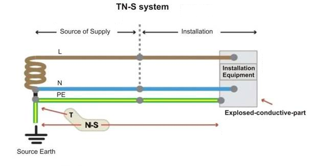
Figure 1 – TN-S System
In order to meet the previous functions three fundamental features are enhanced:
- Conductive capacity;
- Low resistance value;
- Configuration of an electrode that enables the potential gradient control.
Regardless of its protective or functional aim, grounding must be a single one on each installation spot. There are situations where earthing wires may be separated, however with precautions.
In relation to the installation of grounding system components some criteria must be obeyed:
- the grounding resistance value must not be too modified throughout time;
- the components must resist to thermal, thermo-mechanical and electronic conditions;
- the components must be robust or mechanically protected to meet external influence conditions;
- avoid damages to electrodes and other metal parts from electrolysis.
Equipotentialize
Definition: Equalize with the same potential.
In practice: Minimize the potential difference to reduce accidents.
Each building must have a principal equipotentialization and the installation masses located in the same edification must be connected to the main one, thereby creating the same and only grounding electrode. See figures 2 and 3.
The functional equipotentialization equalizes the grounding and guarantees that the signal circuits and the electromagnetic compatibility work well.
Conductor for Equipotentialization
- Main – there must be at least half section of the protection conductor with the largest section and at least:
- 6mm2 (Copper);
- 16mm2 (Aluminum);
- 50mm2 (Steel)
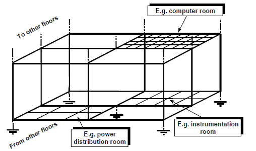
Figure 2 - Equipotentialization
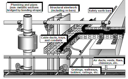
Figure 3 – Grounding Line and Equipotential
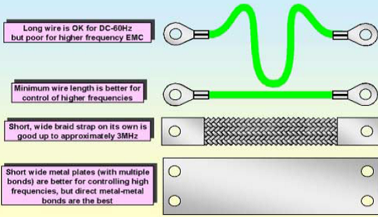
Figure 4 – Equipotential Material
Considerations about equipotentials
Figure 5 shows a generating source for high voltage and high frequency noises, besides a system for temperature measuring 23 m distant from the control room. Depending on how the signals are accommodated there might be up to 2.3KV at the measuring terminals. As the conditions for shielding, grounding and equalization improve, we reach the ideal measuring conditions.
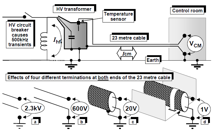
Figure 5 – Example of how important are grounding and equipotentialization and their influence on the signal
In distributed systems like industrial process control, with distant physical areas and power supplied by different power sous, it is recommended grounding on each location and to apply EMI control techniques on each signal routing, as shown on figure 2.
Implications of poor grounding
The implications of poor or even inadequate grounding are not limited to safety aspects. The main effects of inadequate grounding are electric shocks to users through contact, low or intermittent response from the protection systems, such as fuses, circuit breakers etc.).
However, other operational problems may be caused by inefficient grounding:
- Communication failures.
- Drifts or derivations, measuring errors.
- Excessive EMI generated.
- Abnormal heating on the powering stages (inverters, converters etc.) and motorization.
- Frequent computers locking.
- Burning of electronic components without apparent motive, even on reliable equipment.
- Intermittences.
- Other.
The grounding system must be single and must satisfy different purposes:
- Control electromagnetic interference, both internal (capacitive, inductive and common impedance coupling) and external to the system (environmental);
- Operational safety, with the equipment housings connected to the earth, when any signal directly or indirectly grounded or referenced to the housing or the panel is automatically referenced to the power source grounding;
- Protection against lightning, when the descending conductor of the Atmospheric Discharges Protection System must be connected to the power source gronding, metal piping etc., while the “circuitry earth” remains connected to the “lightning rod earth” via the electrode structure or system.
The result is that equipment with metal housing is subject to noise on the power source and lightning grounding loops.
In order to meet the safety standards and protection against lightning and EMI the grounding system should be a zero impedance plan, whose mixture of different current levels would turn these systems free from interference. This would be the ideal condition, one that, however, is not necessarily true in practice.
Types of Grounding
In terms of process industry the following grounding types can be identified:
- “Dirty grounding”: Those in installations that typically involve 127VAC, 220VAC, 480VAC and are associated to high commutation level, such as the MCCs, lighting, power distribution etc, namely, EMI generating sources. Primary AC power supply usually presents peaks, surges, the so-called spikes that degrade the AC ground..
- “Clean grounding”: Those in typically 24VDC DC systems and circuits powering PLCs, controllers having signals of acquisition and data control in addition to digital networks.
- “Structural grounding”: Grounding through a structure that forces the signal at OV. It typically functions as the Faraday cage and protects against lightning.
Note: the “chassis” or “housing” grounding is used as a protection against electric shock. This type of grounding is not a zero-resistance type and its potential may vary. However, the loops are mostly connected to the ground to prevent shock risks.
Single-point grounding
The grounding system at a single point can be seen on figure 6, whose striking feature is a single grounding point evenly distributed to the entire installation.
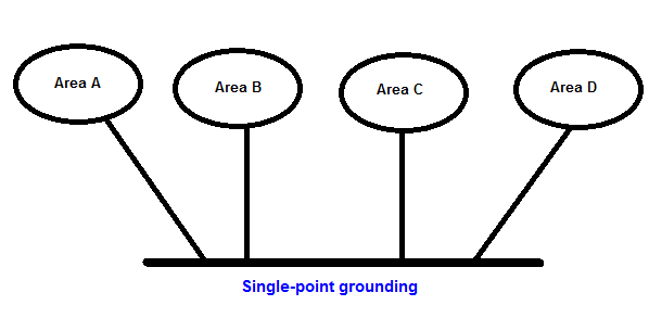
This configuration is best suitable for low-frequency spectrum and satisfies perfectly high frequency electronic systems installed in reduced areas.
Moreover, this system must be insulated not to work as a return path for signal currents circulating through signal conductors with balanced pair, for example.
This type of parallel grounding eliminates the common impedance problem, although detrimental to the use of a pile of wiring. Furthermore, the impedance on each wire may be too high and the ground lines may become a source of noise in the system. This situation may be minimized by choosing the right type of conductor (AWG 14 type). Cables with thicker gauge help reduce the ground resistance, while the flexible wire reduces the earth impedance.
Multiple-point grounding
For high frequencies, the multipoint system is the most adequate and simplifies the installation, as shown on figure 7.
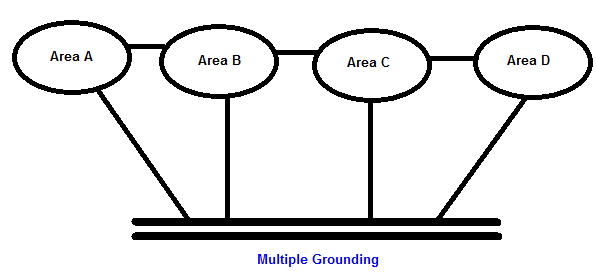
Figure 7 a – Multipoint grounding
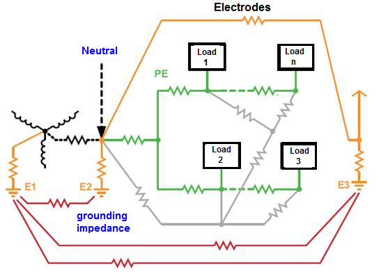
Figure 7 b – Grounding in practice
Many low impedance connections between the PE conductors and the grounding electrodes combined with multiple-impedance paths between the electrodes and the impedance on conductors create a complex grounding system with an impedance network (see figure 7 b), and the currents that flow through it cause different grounding potentials on the the network interconnections.
The multipoint grounding systems that use balanced circuits normally do not have noise problems due to filtering, where the noise field is limited between the cable and the grounding plan.
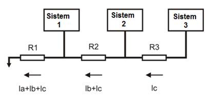
Figure 8 – Inadequate multipoint grounding
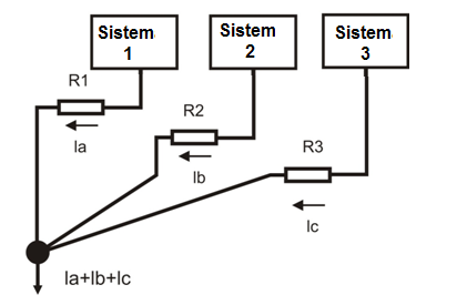
Figure 9 – Inadequate single-point grounding
Figure 9 shows adequate grounding whose individual currents are conducted to a single grounding point.
Serial grounding connection is very common because it is simple and economical. However, this grounding provides a “dirty ground” due to the common impedance between the circuits. When the circuits share the same ground wire, the circuit currents that flow through the finite impedance of the common base line may cause ground potential variations on the other circuits. If the currents are large enough, the potential variations may cause serious disturbances on the operation of all the circuits connected to the common signal ground.
Grounding loops
A grounding loop occurs when there is more than a grounding path, which generates undesirable currents between these points.
These paths form the equivalent to an antenna loop that captures the interference currents with high efficience.
Consequently, the voltage reference becomes unstable and the noise appears on the signals.
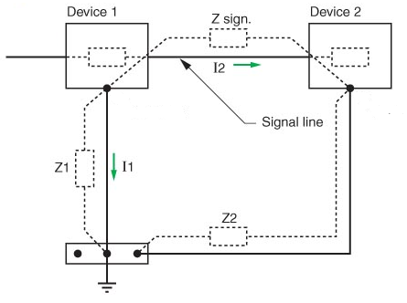
Figure 10 – Grounding loop
Grounding at equipment level: Practice
In practice, the resource is to use a “mixed system” that separates similar circuits and segregates those with the noise level:
- “signal ground” for more sensitive circuits;
- “noise ground” for commands (relays), high potency circuits (MCCs, for example).
- “equipment ground” for rack , panel grounding, etc.These three circuits are connected to the protection conductor.
These three circuits are connected to the protection conductor.
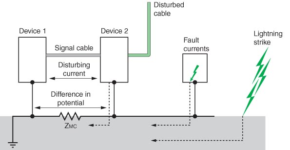
Figure 11 – Grounding at equipment level in practice
The signals may vary basically due to:
- Voltage Fluctuation;
- Current harmonics;
- Conducted and radiated RF;
- Transitories (conduction or radiation);
- Electrostatic Fields;
- Magnetic Fields;
- Reflections;
- Crosstalk;
- Atenuations;
- Jitter (phase noise);
- Other.
The main sources of interference are:
- Capacitive coupling (interaction of electric fields between conductors);
- Inductive coupling (accompanied by a magnetic field. The level of disturbance depends on the (di / dt) current variations and the mutual coupling inductance;
- Conduction through common impedance (grounding): It occurs when the current on two different areas pass by the same impedance. An example is the two-system common grounding path.
Capacitive Coupling
The capacitive coupling is represented by the interaction of electric fields between conductors. A conductor passes near a noise source (the disturber), captures this noise and sends it to another part of the circuit (the victim). This capacitance effect between two bodies with electric loads separated by a dielectric is called mutual capacitance effect.
The electric field effect is proportional to the frequency and inversely proportional to the distance.
The level of disturbance depends on the voltage variations (dv/dt) and the value of the coupling capacitance between the “disturber cable” and the “victim cable”.
The coupling capacitance increases with:
- The frequency reverse: The capacitive coupling potential increases as the frequency increases (the capacitive reactance, which may be considered as the capacitive resistance, decreases according to the frequency and may be seen on the formula XC = 1/2πfC).
- The distance between the disturber and the victim cables and the length of the cable that runs alongside them.
- The cable height in relation to the reference plan (relatively to the soil).
- The impedance of the victim circuit input (circuits of high input impedance are more vulnerable).
- The victim cable insulation (cable insulation εr), mainly for strongly coupled cable pairs.
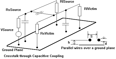
Figure 12 a – Capacitive coupling effect
.png.jpg)
Figure 12 b – Example of capacitive coupling effect
Figure 13 shows the coupling and its voltage and current sources in common and differential modes.
Differential Mode Common Mode Source Victim
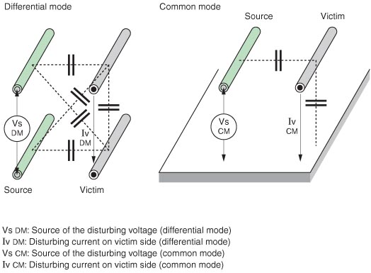
Figure 13 – Differential mode and common mode – Capacitive coupling
Measures to reduce the capacitive coupling effect
- Limit the cable length that runs in parallel
- Increase the distance between the disturber cable and the victim cable
- Ground one of the shield ends on both sides
- Reduce the disturber signal on the dv/dt by increasing the signal peak whenever possible (lower the signal frequency)
Always wrap the conductor or equipment with metal material (Faraday shield). The ideal is to cover 100% of the protected part and to ground this shield so that the parasite capacitance between the conductor and the shield does not function as a repowering or crosstalk element. Figure 14 shows the interference between cables whose capacitive coupling induces voltage transients, such as electrostatic pickups. In this situation the interference current is drained by the shield to the ground, without affecting the signal levels.
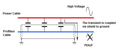
Figure 14 – Interference between cables: the capacitive coupling between cables induces voltage transients (electrostatic pickups)
Figure 15 shows an example of protection against transients.
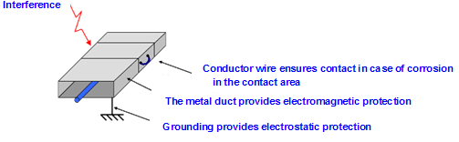
Figure 15- Example of protection against transients (best solution against Foucault current)
How to reduce electrostatic interferences:
- Adequate grounding and shields
- Optical Insulation
- Use of conduits and grounded metal boxesFigure 16 shows the capacitance on the coupling between two conductors separated by a D distance.
Figure 16 shows the capacitance on the coupling between two conductors separated by a D distance.
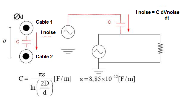
Figure 16 – Capacitive coupling between conductors at a D distance
Inductive Coupling
The “disturber cable” and the “victim cable” are followed by a magnetic field. The level of disturbance depends on the current variations (di/dt) and the mutual coupling inductance. The inductive coupling increases with:
- The frequency: the inductive reactance is directly proportional to the frequency (XL = 2πfL)
- The distance between the disturbing and victim cables and the cable lengths running in parallel
- The height of the cables in relation to the plan of reference in relation to the soil
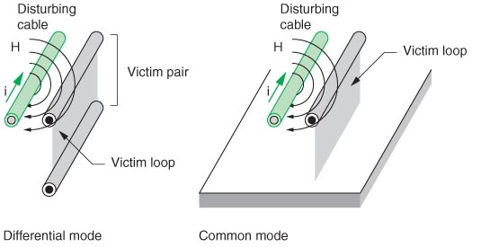
Figure 17 a – Inductive coupling between conductors
Measures to reduce the inductive coupling effect between cables
- Limit the length of cables running in parallel
- Increase the distance between the disturber cable and the victim cable
- Ground one of the shield ends between the two cables
- Reduce the dv/dt on the disturber cable by increasing the signal peak, whenever possible (resistors connected in series, PTC resistors on the disturber cable, ferrite rings in the disturbers and/or the victim cable)
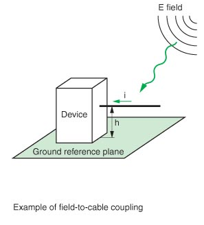
Figure 18 – Inductive coupling between cable and field
Measures to reduce the inductive coupling effect between cable and field
- Limit the cable “h” height to the gound plan
- Whenever possible install the cable close to the metal surface
- Use twisted cables
- Use ferrites and EMI cables
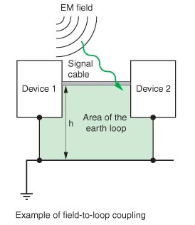
Figure 19 – Inductive coupling between cable and ground loop
Measures to reduce the effect of the inductive coupling between cable and ground loop
- Reduce the “h” height and the cable length.
- Whenever possible locate the cable near the metal surface.
- Use twisted wires.
- In high frequencies ground the shield on two points (caution!) and in low frequencies on a single point.
|
|
Digital Communication Cable |
Cables with and without shield: 60Vdc ou 5Vac e < 400Vac |
Cables with and without shield> 400Vac |
Any cable subject to lightning exposure |
|
Digital Communication Cable |
|
10 cm |
20 cm |
50 cm |
|
Cables with and without shield: 60Vdc ou 25Vac e< 400Vac |
10 cm |
|
10 cm |
50 cm |
|
Cables with and without shield: > 400Vac |
20 cm |
10 cm |
|
50 cm |
|
Any cable subject to lightning exposure |
50 cm |
50 cm |
50 cm |
|
Table 1 – Distances between digital communication cables and other types of cable to ensure EMI protection
Electromagnetic Interferences can be reduced with:
- Twisted cable
- Optical Insulation
- Use of grounded metal ducts and boxes
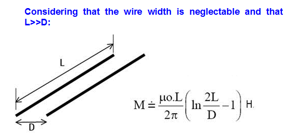
Figure 21 – Mutual inductance between two conductors
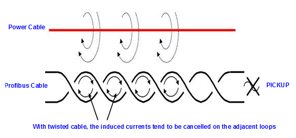
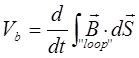
To minimize the induction effect use the twisted pair cable that reduces the (S) area and the Vb inducted voltage in function of the B field, thereby balancing the effects (average of the effects according to distances):
The twisted pair cable is formed by two pairs of wire. The one-pair wire is wound in spiral and through the cancellation effect reduce the noise and keep the medium electric properties constant through its whole length.
The reduction effect by using twisted wires is efficient for cancelling the flow, called Rt (in dB):
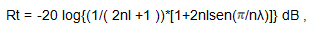
where n is the number of turns per meter and l is the cable total length. See figure 22a and figure 22b.
The cancelling effect reduces the crosstalk between the twisted pairs and the level of electromagnetic/radiofrequency interference. The number of wire twists may vary for reducing the electric coupling. Its construction provides a capacitive coupling between the pair conductors. It works more efficiently in low frequencies (< 1 MHz). When not shielded, it has the disadvantage with common-mode noise. On low frequencies, i. e., when the cable length is smaller than 1/20 of the wave length of the noise frequency, the shield will present the same potential along its entire extension, and the shield should be connected on a single ground point. On high frequencies when the cable length is longer than 1/20 of the wave length of the noise fequency, the shield will present high sensibility to noise and the grounding on both shield ends is recommended.
On the inductive coupling we will have Vnoise = 2πBAcosα where B is the field and α is the angle where the flow crosses the area (A) vector, or still in function of the mutual M inductance: Vruído = 2πfMI, whose I is the current on the power source cable.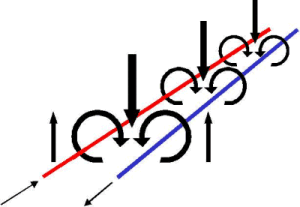
Figure 22 a – Inductive coupling effect in parallel cables
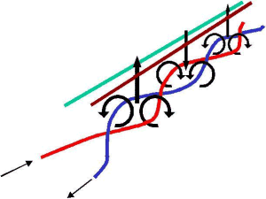
Figure 22 b – Minimization of the inductive coupling effect in twisted cables
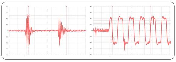
Figure 22 c – Example of inductive noise
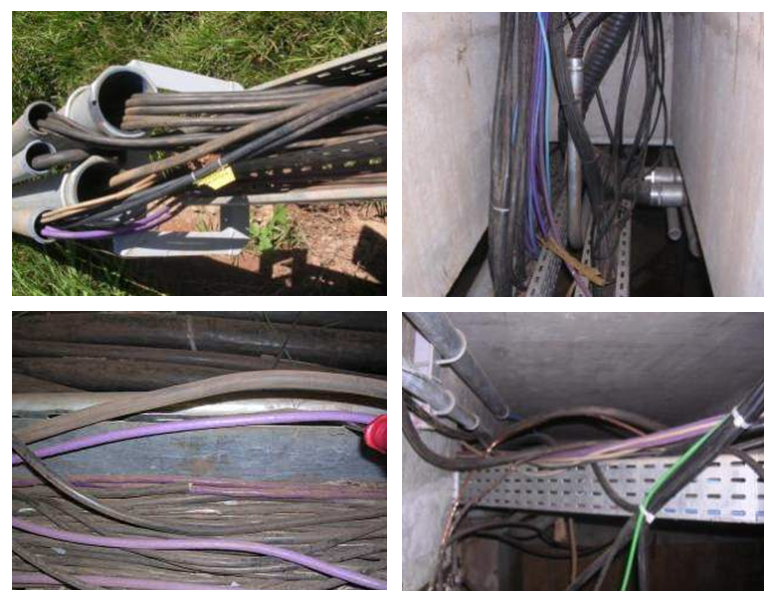
Figure 22 d – Example of Profibus Cables near the power source cable
The use of twisted pair cables is very efficient as long as the induction in each tortion area is approximately equal to the adjacent induction. Its use is efficient in differential mode, balanced circuits and has low efficiency in low frequencies on unbalanced circuits. In high frequency circuits with grounded multipoints, the efficiency is high, since the return current tends to flow through the adjacent return. However, in common mode high frequencies the cable has little efficiency.
Figure 23 details the Profibus-DP and the ground loops situation.
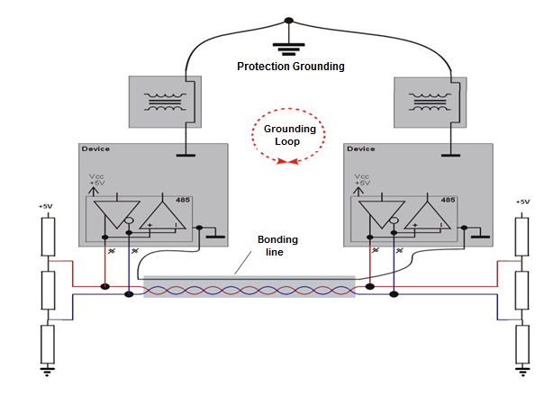
Figure 23 – Profibus-DP and the ground loops
Protection with metal ducts
Following is the use of metal ducts to minimize Foucault currents.
The spacing between ducts induces the magnetic field to generate disturbances. In addition, this discontinuity may help ease the difference of potential between each duct segment, and, in the event of current surge generated by an atmosphere discharge or a short circuit, the lack of continuity will not allow the current to circulate along the aluminum duct and consequently will not protect the Profibus cable.
The ideal is to connect each segment with the largest possible contact area to provide more protection against electromagnetic induction and also a conductor between each segment on each duct side, with the shortest possible length to ensure an alternative path to the currents, in case of the increase of resistance at the segment joints.
If the aluminum duct is properly mounted, when the magnetic field penetrates on the aluminum plate will produce inside it a a magnetic flow that varies in function of the time [f = a.sen(w.t)], creating an induced f.e.m. [ E = - df/dt = a.w.cos(w.t)].
In high frequencies the f.e.m induced on the aluminum plate will be higher, originating a larger magnetic field and will cancel almost completely the magnetic field generated by the power source cable. This cancellation effect is smaller in low frequencies. In high frequencies the cancellation is more efficient.
This is the effect of metal plates and screens on the incidence of electromagnetic waves; they generate their own fields that minimize or even nullify the field through them, therefore working as true shields against electromagnetic waves. They work as a Faraday cage.
Make sure that the plates and the coupling joints are made with the same material as the cable ducts/boxes. Protect the connecting points against corrosion after mounting with zinc paint or varnish.
Although the cables are shielded, the shielding against magnetic field is not as efficient as against electrical cables. In low frequencies, the twisted pair absorbs most parts of the effect from electromagnetic interference. In high frequencies these effects are absorbed by the cable shield. Whenever possible, connect the cable boxes on the equipotential line system.
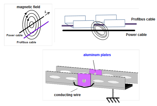
Figure 24 – Protection of transients with the use of metal ducts
Transient and effective distances protectors
In regard to projects and installations we must be aware when dealing with concepts and techniques for the protection of PROFIBUS DP and PROFIBUS PA field equipment in terms of high voltage signals and induced lightning or other sources.
It is public knowledge that control systems installations may include of air distribution and underground cables, wire boxes, cables near to high voltage cables subject to the exposition to lightning, electrostatic discharges and electromagnetic interference (EMI). EMI may be radiated (via air), conducted (via conductors), induced (above 30 MHz) or a combination of these means. For an idea of the voltage generated by electrostatic discharge, if we consider a conductor with 50nH of inductance, it may include voltage peaks around 200V (V=L*dj/dt) or more, since the current pulse generated by the electric discharge has a very short upward time, approximately 4A/ns.
This exposition can affect the behavior of the signals and damage the equipment, as long as they have the same low power components and may easily burn with the overvoltage.
What is a transient protector?
The transient protector is a protection hardware that, properly positioned (as we will see next) and installed, protects the equipment by limiting the level of the transients that could reach it. It works almost instantaneously and “deviate” the transient to the ground and controls the voltage at a level that does not damage the equipment connected to it. When the current reaches an acceptable level, the normal operation is automatically reestablished.
A large variety of models is sold in the market. These protection devices are based on a combination of components like gas discharge tubes (GDTs, or surge arresters, cutting diodes (clamping voltage) and metal-oxide varistors (MOVs) whose features are fast operation, precise voltage control and automatic return, as soon as the overvoltage stops.
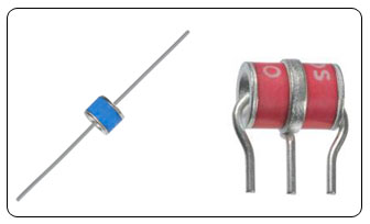
Figure 25 – Surge Arrester
How to protect PROFIBUS PA networks and equipment
In PROFIBUS PA installations, the voltages exceeding normal operation conditions are known as ‘surges’. They appear transitorily and may affect the network behavior. It is worth mentioning that as every fieldbus network, they exchange data and, most importantly, they guarantee the integrity of the data and the plant operational safety.
The longest the PROFIBUS PA network trunk and derivations, the larger will be the magnitude of transients due to the ground potential difference. Significant damage can be caused in equipment connected by short cables if the circuits or components are particularly sensitive. In some situations, there may be serious damage on the installation and the equipment, depending on the energy.
The standard PROFIBUS PA network cable is the twisted pair type, whose twisted conductors minimize the voltage between lines, although, as mentioned before, the ground potential difference may damage the components and affect their work, thereby turning the system sensitive. Also notice that the cable and its distribution are factors to be considered to minimize noises and transients. The use of shield is recommended, as it acts as a Faraday cage, and when grounded at the source of signal it maximizes its efficiency against noises in common mode. Furthermore, it provides better EMI protection.
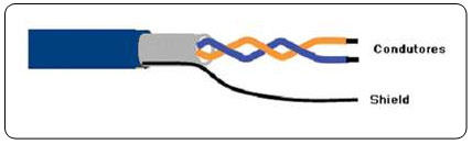
Figure 26 – PROFIBUS PA twisted pair cable
Concerning the transient protector, the limit voltage must not be higher than the equipment work voltage and in practice this voltage is used as twice that of the equipment. In terms of lightning, studies show that the discharges may generate currents from 2 kA to 200 kA on the peak currents lasting less than 10μs.
The choice of the transient protector must be judicious, as it can degrade the PROFIBUS PA signal and limit the quantity of equipment. Depending on the manufacturer, this device may add capacity and resistance to the PROFIBUS PA network and these may affect the communication wave signal. Furthermore, some cutting diodes could not be transparent on the network and could also affect the signal levels. In practice, the user should choose devices that comply with the IEC 61643-21 standard and provide high surge currents (around 10 kA), while adding less than 1? and less than 40pF to the wiring.
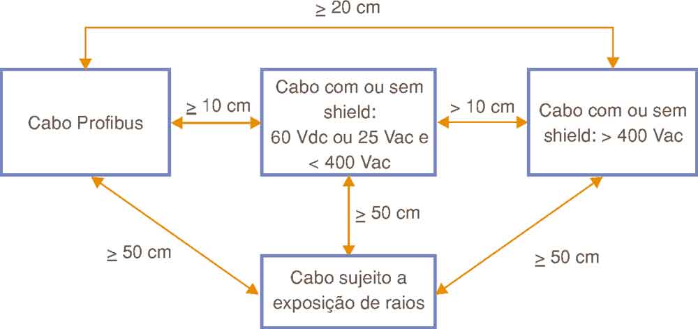
Figure 27 – Distances recommended in PROFIBUS wiring
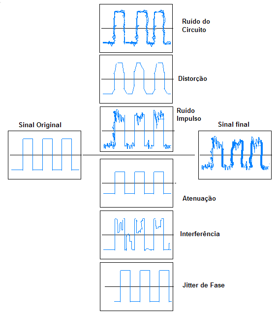
Figure 28 – Degree of interference on a Profibus signal.
The degree of cable interference will depend on a series of factors such as project, construction and characteristics, in addition to their interaction with other elements on the PROFIBUS network (connectors, equipment, shielding, other cables, etc.) besides certain system parameters and environment properties. A variety of factors limit the performance of the digital signals transmitted related to the cables, which should be considered in the project and their use, such as:
- attenuation;
- noise, the following types:
o differential noise (circuit characteristics);
o longitudinal noise (interference due to electric power supply);
o impulse noise;
o diaphony (crosstalk);
o distortions by propagation delay;
o jitter (phase noise).
What is effective distance?
Effective distance is the physical separation of two devices grounded during the network installation. Whenever the effective distance is bigger than 100 m on the horizontal or 10 m on the vertical between two grounded points, transient protectors are recommended at the initial and the final distance points. In practice, the use is recommended between 50 and 100 m.
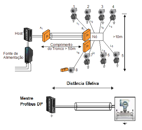
Figure 29 – Use of transient protector and the effective distance.
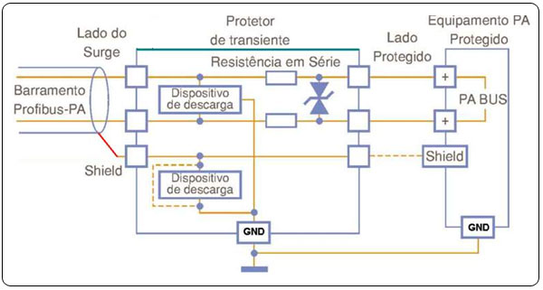
Figure 30 – Example of PROFIBUS PA protector transient.
How to protect PROFIBUS DP networks and equipment
The rule for effective distance also applies to the PROFIBUS DP network and equipment.
According to figure 31, protection will be provided in case of tension drop or when a surge or even any differential surge should exceed the breakdown voltage. According to figure 32, this protection is recommended when grounding is not possible and any differential surge will be converted into common mode.
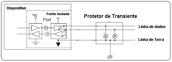
Figure 31 – Protection with ground insulation.
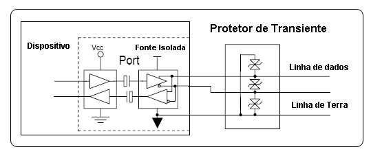
Figure 32 – Protection with common-mode insulation.
Interferences
The interferences on digital network cables and the instrumentation may be due to:
- Capacitive coupling
- Electromagnetic coupling
Electrostatic interferences may be reduced by:
- Adequate grounding and shielding
- Optical insulation
- Use of grounded metal conduits and boxes
Electromagnetic Inferences can be reduced with:
- Twisted cables
- Optical insulation
- Use of grounded metal conduits and boxes
- CCM repeaters with galvanic insulation, by insulating the groundings.
Basically there are 4 types of interferences:
- Line noise
o Generated by an electromagnetic source
o Corona Effect, Line Noise and Sparking
- Overload
o Generated by the signal fundamental
- Spurious emissions
o Signal harmonics or undesirable signals
- Generated by the Architecture and the Project
Let us now comment on the Corona effect. Inverter cables load the energy of the speed control motor into the AC motor. These cables should support not only the high power from the MLP signals (Modulation of Pulse Width), but also the voltage that occurs when the stationary waves develop in the conductors because the cable impedance does not match the motor impedance and that from modern switching inverters. The high voltage may cause Effect Corona discharges and damage the cables and the inverter variable startup.
Currently, special cables use a thicker, electrically more stable insulation. The insulation increases the distance between the conductors and decreases the danger of a Corona Effect discharge. In addition, by reducing the capacitance, the amplitude of the stationary waves is reduced, as well as the transference of noises to the ground loop.
Profibus grounding, shielding and equipotentialization
The ideal grounding condition in a plant and its installations is when the same potential is found in any point. This may be reached by connecting all its grounding systems through a potential equalization conductor. This condition is known as equipotentialization.
So, any person inside a facility will be free from electric shock, even if the existing voltages increase, because every element will have the same ground potential.
When referring to shielding and grounding, in practice there are other ways of dealing with this subject - a very controversial one - such as, the shield grounding can be done in each station through the 9-pin sub D connector, whose housing touches the shield at this point and it is grounded when connected. This situation, however, should be analyzed timely and the potential graduation of the groundings checked at each point and equalized. The equipotential line system is used to balance the ground potential in different plant locations so that no current circulates over the cable shield.
♦ Copper: 6 mm²
♦ Aluminum: 16 mm²
♦ Steel: 50 mm²
In hazardous areas always observe the recommendation from the certifying organs and the installation techniques required by the area classification. An intrinsically safe system must have components to be grounded and others not. Grounding has the function to avoid unsafe voltages from appearing in classified areas. Avoid to ground intrinsically safe components unless required for functional purposes when using galvanic insulation. The minimum insulation established by standards is 500 Vca. The resistance between the ground terminal and ground system must be below 1Ω. In Brazil, the installation in potentially explosive atmospheres is regulated by the NBR-5418 standard.
For grounding, it is recommended grouping circuits and equipment together with similar noise characteristics in serial distribution and uniting these points on a parallel reference. Always ground conduits and boxes.
- Use copper cables or galvanized grounding tapes on the equipotential line in the system and between the system components.
- Connect the equipotential line to the grounding terminal or to the bus with a wide surface area.
- Connect all ground and shield connections to the equipotential line system.
- Connect the mounting surface (e.g. the cabinet panel or mounting rails) to the equipotential line system.
- Whenever possible, connect the network equipotential line system to that of the facilities.
- If the parts are painted, remove the paint on the connection point before connecting.
- Protect the connection point against corrosion after mounting, using zinc paint or varnish.
- Protect the equipotential line against corrosion. An option is paint the points of contact.
- Use safety screws or terminal connections for every ground and surface connection. Use pressure washers to prevent the connections from getting loose due to vibration or movement.
- Use terminals on the equipotential line flexible cables. The cable ends should never be covered with stain (no longer permitted by regulations).
- Locate the equipotential line router the closest possible to the cable.
- Connect the individual metal parts of the boxes to one another. Use special bonding links or specific jumpers. Make sure the bonding links are made from the same material as the cable boxes. The cable box manufacturers may supply the due links.
- Whenever possible, connect the metal cable boxes to the equipotential line system.
- Use flexible bonding links to expand the joints. The bonding links are supplied by the cable makers.
- For connections between buildings or between building sections, the equipotential line route must be directed parallel to the cable. Keep the following minimum transversal sections, compliant to IEC 60364-5-54:
In hazardous areas always observe the recommendation from the certifying organs and the installation techniques required by the area classification. An intrinsically safe system must have components to be grounded and others not. Grounding has the function to avoid unsafe voltages from appearing in classified areas. Avoid to ground intrinsically safe components unless required for functional purposes when using galvanic insulation. The minimum insulation established by standards is 500 Vca. The resistance between the ground terminal and ground system must be below 1Ω. In Brazil, the installation in potentially explosive atmospheres is regulated by the NBR-5418 standard.
For grounding, it is recommended grouping circuits and equipment together with similar noise characteristics in serial distribution and uniting these points on a parallel reference. Always ground conduits and boxes.
A common error is the use o protection ground as signal ground. Remember that this ground is very noisy and may present high impedance. Recommended is the use of grounding loops, as they have low impedance. Common high frequency conductors present the disadvantage of having high impedance. Current loops should be avoided. The ground system must be regarded as a circuit that supplies the current flow with the least possible impedance. The minimum ground value recommended is below 10 Ω.
The shield (the loop as well as the aluminum blade) should be connected to the functional ground system via the PROFIBUS-DP connector, so that it provides a wide connection area with the conductive surface grounded.
When extending the cable, be careful so that the shield finishing is well done and is not contacting other points unless the grounding points. The maximum protection is at the grounded points, which provide a low impedance route to the high frequency signals.
In cases with a voltage differential between the grounding points, such as different areas in separated facilities, locate a potential equalization line next to the wiring, by using the proper metal conduit or an AWG 10012 cable. (See Figure 33).
This will provide the most effective protection for a wide frequency band.
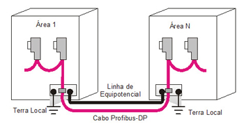
Figure 33 – Equipotential line
Figure 33 – Detail of wiring in different areas with equalized ground potentials
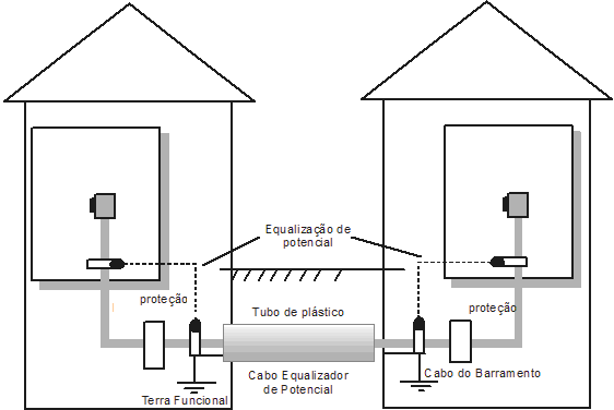
Figure 34 shows wiring, shield and ground details in different areas.
Figure 33 – Detail of wiring in different areas with equalized ground potentials
Profibus-PA network
When considering the question of shield and grounding on fied buses, take into account:
- The electromagnetic compatibility (EMD).
- Protection against explosion.
- Protection of people.
According to IEC 61158-2, to ground means to be permanently connected to the ground by a sufficiently low impedance and with enough conductive capacity to prevent any voltage from causing damages to equipment or persons. Voltage lines with 0 Volts must be connected to ground and galvanically insulated from the fieldbus bus. The purpose of grounding the shield is to avoid high frequency noises.
Preferably, the shield must be grounded on two points, a the beginning and the end of the bus, provided there is no difference potential between these points and allows the existence and paths to loop currents. In practice, when this difference exists, ground the shield only at a single point, i.e., the power source or the intrinsic safety barrier. Make sure the continuity of the shielded cable is longer than 90% of the cable total length.
The shield must cover entirely the electric circuits through the connectors, couplings, splices and junction and distribution boxes.
Never use the shield as a signal conductor. Always verify the shield continuity until the last PA segment in the segment, with due analysis of the connection and finishing, as it should not be grounded on the equipment housing.
In classified areas, if the equalization potential between the safe and the hazardous areas is not possible, the shield must be connected directly to ground (Equipotential Bonding System) only at the hazardous area side. At the safe area, the shield must be connected by a capacitive coupling, preferably a dielectric solid ceramic capacitor, C<= 10nF, isolation voltage >= 1.5kV).
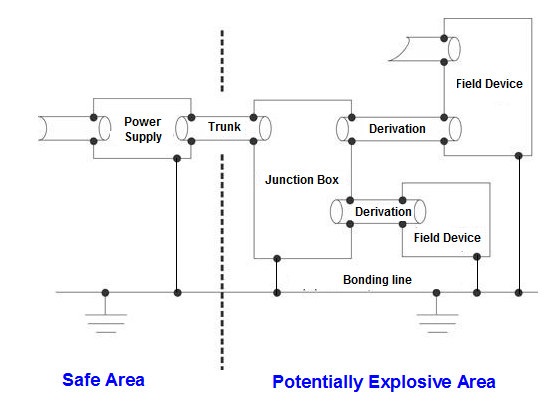
Figure 35 – Shield and Ground Ideal Combination
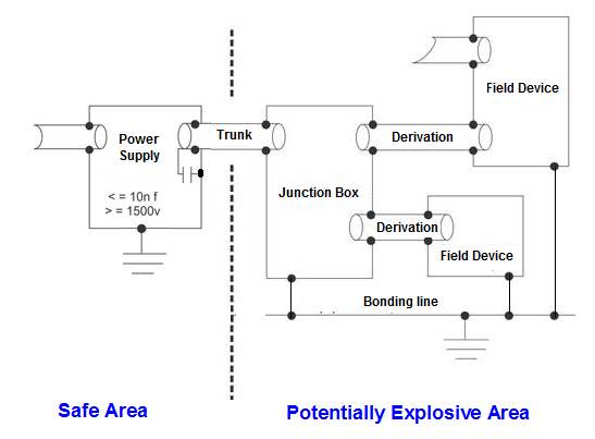
Figure 36 – Capacitive Grounding
The IEC 61158-2 recommends the complete insulation. This method is used mainly in the U.S. and U.K. In this instance, the shield is insulated on all grounds, with exception to the negative ground point of the power source or the intrinsic safety barrier on the safe side. The shield has continuity from the DP/PA coupler output, passes along the junction and distribution boxes and reaches the equipment. The equipment housings are grounded individually on the non-safe side. This method has the disadvantage that it does not protect totally the high frequency signals and, depending on the topology and cable length, may generate occasional communication intermittence. In these cases, the use of metal ducts is recommended.
Another additional manner is to ground the equipment junction boxes and housings on a ground equipotential line on the non-safe side. The grounds on the non-safe and safe sides are separated.
Multiple grounding is also usual and provides more effective protection on situations of high frequency and electromagnetic noises. This method is preferably adopted in Germany and some Europeran countries. In this method, the shield is grounded on the ground point of the power source or the safe side of the intrinsic safety barrier, besides the ground on the equipment junction boxes and housings, and is also grounded on the non-safe side. An additional an complementary situation is one whose grounds would be grounded in a set on an equipotential ground line, connecting the non-safe side to the safe side.
For more details, always refer to the local safety standards. The IEC 60079-14 is recommended as a reference for applications on classified areas.
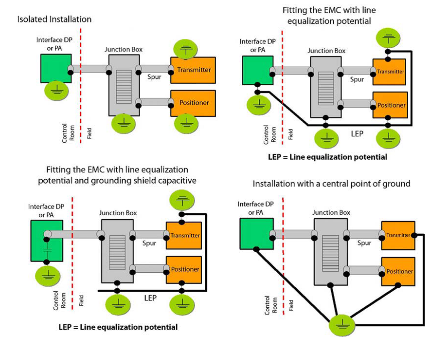
Figure 37 – Grounding and Shield– Several types
Cautions and recommendations with grounding and shield on the PROFIBUS-DP bus
The shield (the loop and the aluminum blade) must be connected to the system functional ground on all stations through the connector and DP cable) to provide a large connection area with the grounded conductive surface.
Maximum protection is provided with all points grounded through a low impedance path to the high frequency signals.
In cases with voltage diferential between the grounding points, pass close to the wiring an equalization potential line (the metal duct or an AWG 10-12 cable can be used). See figure 33.
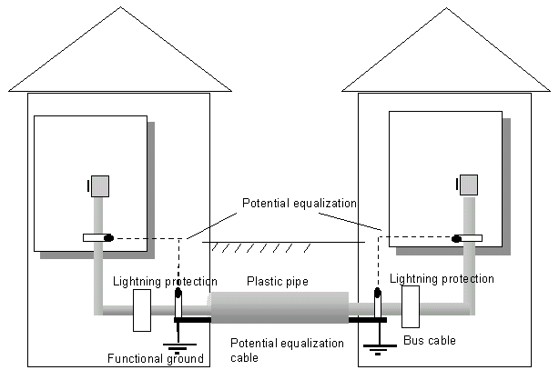
Figure 38 – Equipotential Line
In terms of wiring use the twisted pair of wires with 100% of the shield covered. The best conditions for the shield work are met with at least 80% covered.
When referring to shield and grounding, in practice there are other ways of handling this subject, one with much controversy, as for example, the shield grounding can be made in each station with the sub D 9-pin connector (figure 34), where the connector housing makes contact with the shield and is grounded when connecting with the station. In this case, though, annalyze and verify punctually the ground graduation potential and, if necessary, equalize it.
In hazardous areas always use the recommendations from the certifying bodies and the installation techniques demanded by the area classification. An intrinsically safe system should have components that must be grounded and others not. The purpose of grounding is to avoid occurring unsafe voltages on the classified area. On classified areas, avoid grounding intrinsically safe components, unless it is necessary for functional reasons, when employing galvanic insulation. The standards establish the minimum insulation of 500V resistance between the ground terminal, while the system ground must be lower than 1Ω. In Brazil, the installation on potentially explosive atmospheres is regulated by the NBR-5418.
An extra caution should be taken against excessive termination. Some devices have on-board termination.
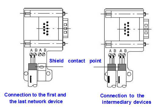
Figure 39 – Detail of a typical Sub D 9-Pin connector
Figure 33 presents wiring, shield and grounding details on multiple areas.
For grounding, group circuits and equipment with similar noise characteristics in serial distribution and connect these points on a parallel reference and also ground ducts and boxes.
A common error is the use of protection ground as signal ground. It is worth noting that this ground is too noisy and may present high impedance. An interesting alternative is the use of grounding loops, as they present low impedance. Common high frequency conductors have the disadvantage of having high impedance and current loops should be avoided. The grounding system should be seen as a circuit that favors the flow of current under the minimum possible inductance. The ground value should be lower than 10 Ω.
Use of shielded cables to minimize noises
In order to provide better efficiency against noises, the double shield (twist and foil) has been applied with considerable improvement in the signal/noise relationship. The following can be added:
· Double protection most certainly provides more efficiency, in some cases even three-fold. The more closed the loop, the better the protection.
· The twisted shield and the foil can be applied in different ways, for low and high frequencies.
For low frequencies the cable is grounded in only one of the ends and in these frequencies the shield is expected to present the same potential. This would provide more protection in low-frequency noises.
For high frequencies the shield will present high susceptibility to noise and both ends should be grounded, although some precaution should be taken due to equipotentiality and safety.
This double protection alternative would protect both low and high frequencies, providing better EMI protection.
The efficacy of the loop (shield) is generally better in low frequencies, while the foil is more efficient in higher frequencies.
Concerning inverters, which normally are a source of noises, an important point is that most of them have commutation frequency ranging from 1kHz to 30 kHz. In addition, some inverter manufacturers state they comply with the CE standards, but that in adequate installations mandatory is:
1. Properly ground, according to manuals, i.e., the shield is grounded on both ends and the motor housing is also grounded (per manufacturers´ recommendation).
2. Output power, control wiring (I/O) and signal must use shielded cable, twisted with original cover equal to or above 75%, with metal conduit or equivalent attenuation.
3. All shielded cables must have their ends in an adequate shielded connector.
4. The control and signal cables must be separated at least 0.3 m from power wiring.
How to understand the Profibus signal reflection
RS485 physical means is the standard with two independent channels known as A and B that transmit equal voltage levels, however with opposed polarity (VOA and VOB) or simply VA and VB).
For this reason, the network must be activated with the correct polarity. Although with opposed signals, one does not work as return for the other, i.e. there is no current loop.
Each signal returns through ground or a third return conductor, but the signal must be read by the receptor in a differential way without reference to the ground or the return conductor.
This is the great advantage of the differential signal concerning ground in this communication system: note on figure 41 that the signal is running with inverted phases on the cable conductors, while the noise runs with the same phase.
On the input terminals of the differential amplifier the Profibus communication signal reaches in differential mode and the noise reaches in common mode, hence rejecting it. Therefore, all noise induced in the cable, generally from electromagnetic origin, will be mostly rejected.
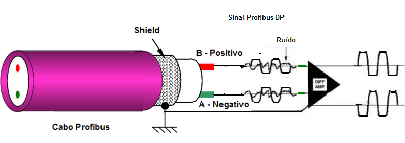
Figure 41 – RS485 Profibus-DP signal
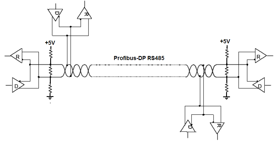
Figure 42 – RS485 Profibus-DP network
Differential transmission lines use as information only the difference of potential that exists between the two twisted pair conductors, regardless of the potential difference presented in relation to voltage referential (common or ground referential).
What is signal reflection?
Signal reflection occurs when a signal is transmitted along a means of transmission such as a copper cable or optics fiber and part of the signal energy may be reflected back to its origin. It may be due to a cable imperfection, change of impedance along the communication line (splices), lack of terminator spur beyond permitted, total length beyond permitted, etc.
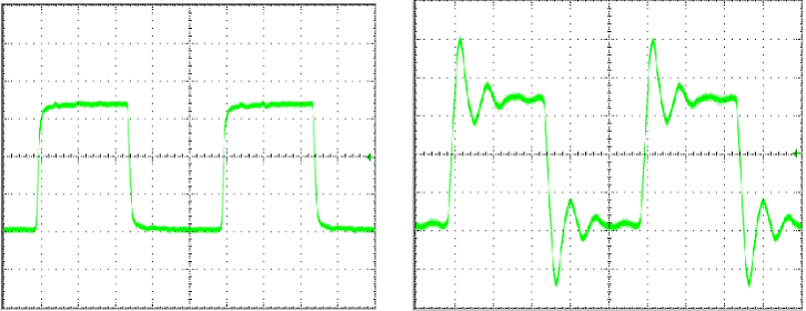
Figure 43 – Profibus signal without reflection (left) and with reflection (right) due to lack of terminator
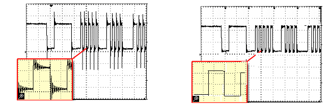
Figure 44- Profibus signal with reflection by splices (left) and without reflection (right).
Note on figure 45 that the largest the communicaton rate, the largest the reflection influence will be, as the bit time is smaller.
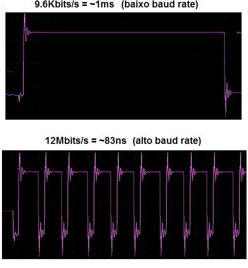
Figure 45 – Profibus signal with reflections in different baud rates.
Figure 47 shows an example of installation whose minimum curve was violated and makes the Profibus signal act like that on figure 48.
Minimum curvature
Flexion, stretching, twisting, crushing while installing the Profibus cable may force the conductors or even alter their transversal sections. This disturbs the common axis of the conductors and their shield, and fakes a change of impedance on the cable stress points. By capturing the signals, these points are easily identified by the reflections on the signals. Nonetheless, the minimum specified radius refers to the cable internal surface and not the cable axis.
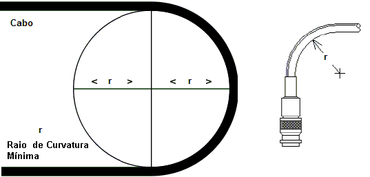
Figure 46 – Minimum Curvature Radius
Frequently the damages are not visible and the cable insulation and integrity may be impaired.
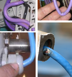
Figure 47 – Examples of inadequate minimum curvatures and damaged cables
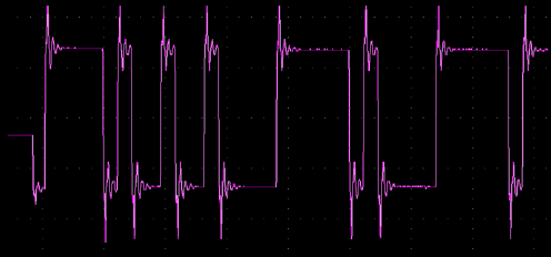
Figure 48 – Profibus signal with reflection due to the violation of the cable minimum curvature
Figure 49 shows the diagram of a basic single-ended transmission line. A voltage source (VS) generates a digital signal with a Zs impedance. The transmission line has the AC impedance ZO in relation to the ground and at the cable end there is the ZT impedance, for impedance matching. Profibus has a terminator at the beginning and the end of each segment that guarantees the best signal condition.
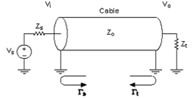
Figure 49 – Diagram of a basic (single ended) transmission line
What is a network terminator?
The terminator is an impedance added to the Profibus line with the function of matching the network impedance. The longer the network length is, the bigger the signal distortion. The terminator eliminates communication errors caused by the distorted signals. If the terminator is not installed, the wiring will work as an antenna, hence facilitating signal distortions and increasing the susceptibility to noises. The characteristic impedance is the load value, which placed at the end of this line does not reflect any energy. In other words, it is the load value that provides the zero reflection coefficient, or still, a relation of stationary waves equal to one.
Without any terminators at the Profibus segment, the resulting signal in the load is distorted in time (jitter) and amplitude (oscillations). Every time the cable geometry is altered it will cause unbalanced impedance and resulting reflections.
Both Profibus-DP and Profibus-PA networks require terminators. The use of a bus terminator is mandatory where its absence may cause unbalance, with the resulting propagation delay, as well as the damped resonance oscillations cause the transposition of the logical level (thresholds). In addition, the static noise margin improves. In the Profibus-DP, the terminators are active ones, i.e. they are powered. See figure 50.
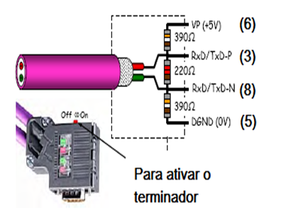
Figure 50 – Profibus-DP bus terminator.
The active termination is needed at the beginning and the end of each bus segment in order to keep the communication signal integrity and both terminator should be powered. See figure 51.
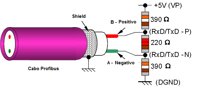
Figure 51 – Profibus-DP active bus terminator.
The Profibus-DP must have bus terminators (a 100 Ohm resistor and a serial 1 uF) one at the beginning and other at the end. The shield must not be connected to the terminator and the impedance must be 100 ohms +/-20% from 7.8 to 39 kHz. This value is approximately the average value of the characteristic cable impedance on the work frequencies and it is chosen to minimize the transmission line reflections, as well as to convert the signal in acceptable 750 to 1000 mV levels.
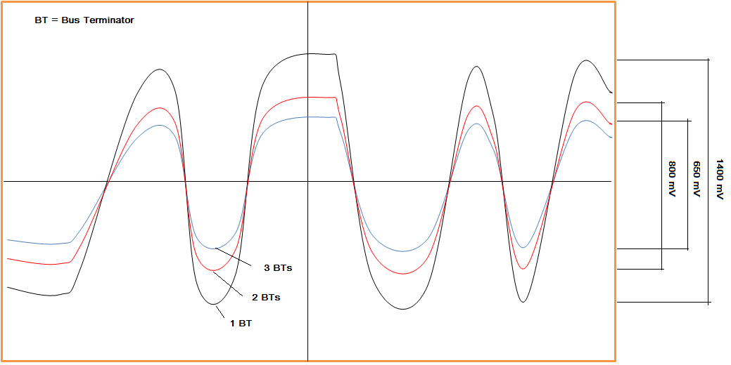
Figure 52a – Typical PA network wave form and the influence of the terminators.
Figure 52b – PA terminator with signals of humidity: wrong termination.
Necessary care with the Profibus-DP network terminators
As terminators are active devices, a common error is to place the work stations as a DP slave where an energy drop or a microcomputer is reset, causing unbalance on the power supply lines, intermittence and undesirable timeouts.
Shielding
Grounding and shielding are mandatory requirements to guarantee the integrity of a plant data. In practice, it is very common to watch intermittent work and gross errors in measurements due to the bad installations.
Noise effects can be minimized with adequate techniques of projects, installation, cable distribution, grounding and shielding. Inadequate grounding may be the source of undesirable and dangerous potentials that may endanger the effective operation of an equipment or the work system itself.
The shield must be connected to the signal reference potential of what is being protected (see figure 53).
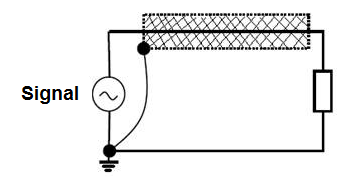
Figure 53 – Shielding connected to the signal reference potential it protects
When there are multiple segments keep them connected, ensuring the same reference potential, according to figure 54.
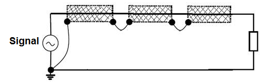
Figure 54 – Multiple-segment shielding connected to the signal reference potential it is protecting
Grounding effect vs. Single-point grounding
In this case the current will not circulate through the loop and will not cancel the magnetic fields. The length of the conductor extending outside the shield should be minimized and guarantee good connection between the ground and the shield.
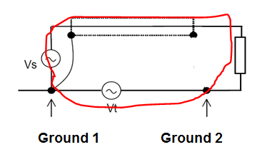
Figure 27- Grounding Effect vs single-point grounding
Grounding effect vs Two-point grounding
A distribution of currents occurs here, in function of the frequencies, since the current tends to follow the course of lower impedance.
Up to a few kHz: the inductive reactance is neglectable and the current will circulate by the way of less resistance.
Above kHz: the inductive reactance predominates and this will make the current circulate by the way of less inductance.
The way of less impedance is that whose course of return is close to the course of departure for presenting distributed capacitance and lower distributed inductance.
The length of the conductor extending outside the conductor should be minimized and guarantee good connection between the the shield and the ground.
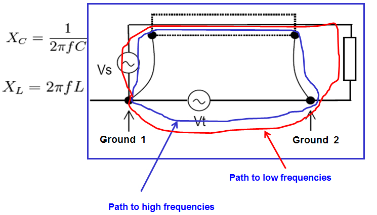
Figure 28 - Grounding effect vs two-point grounding
It is worth mentioning in this case:
- There is no protection against ground loops.
- Significant damages may be caused to active equipment when the ground potential difference between both ends goes beyond 1 V (rms).
- The grounding electrical resistance should be the lowest possible on both segment ends to minimize the ground loops, mainly in low frequencies.
The cable grounding is used to eliminate interferences by capacitive coupling due to electrical fields.
The shielding is only efficient when it establishes a low impedance path to the ground.
A floating shielding does not proctect against interferences.
The grounding loop must be connected to the ground reference potential that is bening shielded.
Ground the shield on more than one point may be problematic.
Minimize the length of the shield-reference connection, as it works as a coil.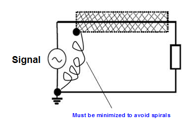
Figure 29 – The length of the ground-reference connection should be minimized as it works as a coil.
- Electric fields are much easier to shield than magnetic fields and the use of shielding on one or more points work against electric fields.
- The use of non-magnetic metals around conductors does not shield against magnetic fields.
- The key to magnetic shielding is to reduce the loop area. Use a twisted pair or the return of current thtrough the shield.
- To prevent radiator from a conductor, a grounded shield on both sides is generally used above the cut frequency, but some precautions must be taken.
- Only a limited amount of magnetic noise can be shielded due to the ground loop formed.
- Any shielding through which noise flows must not include the signal path.
- Use a shielded twisted cable or a triaxial cable on low frequencies.
- The effectiveness of the twisted cable shield increases with the number of turns per cm.
Some general rules concerning control panels, MCCs and instrumentation
- Use RFI filter and always connect it the closest possible to the noise source (between the RFI filter and the drive).
- Never mix input and output cables.
- All motors activated by inverters must be powered preferably by shielded cables grounded on both ends. This is recommended by all inverter manufacturers. Also note that commutation frequencies vary from 1k to 34KHz, usually 30khz, and may have great influence on the Foundation Fieldbus and the Profibus-PA networks .
- Whenever possible, use trafo isolators to power the automation system.
- Use repeaters in MCCs for galvanic insulation, avoiding ground differentials.
- To meet EMI protection requirements all external cables must be shielded, except power source cables. The shield loop must be continuous and not interrupted.
- Make sure that all cables of different zones are routed in separated ducts. Inside the panel create distinct zones and even use separating plates that served as shield.
- Make sure that all cables cross at right angles to reduce couplings.
- Use control cables with the lowest possible transference impedance values.
- On control cables install a small (100 nF a 220 nF) capacitor between the shield and the ground to avoid the return of AC circuit to the ground wire. This capacitor will work as an interference suppressor. But always verify the manufacturer inverter manual.
- Choose toroid inverters or add toroids (common mode chokes) on the inverter output.
- Use isolated and shielded cables (4 paths) between the inverter and the motor and between the inverter power supply along the inverter.
- Try to work with the lowest possible switching frequency.
- Always ground the motor housing. Ground the motor on the panel, where the inverter is installed, or on the inverter itself.
- Inverters generate escape currents and in this case a line reactor can be introduced on the inverter output.
- Line reactors are a simple and inexpensive way to increase the impedance of an isolated load source (as a variable frequency command, in the case of inverters).
- The reactors are connected in series to the load that generates harmonics and, by increasing the source impedance, the magnitude of the harmonic distortion may be reduced to the load where the reactor is added. Here, again, refer to the inverter manual and check the recommendations.
- The ideal is to incorporate an input inductor and a RFI/EMC filter to work as additional protection for the equipment and a as harmonic filter for the electric network, where the equipment is connected.
- The main function of the RFI input filter is to reduce the emissions conducted by readiofrequency to the principal lines of distribution and the ground. The RFI input filter is connected between the input power source AC line and the inverter input terminals.
- Reflected waves: if the cable impedance does not match that of the motor, there will be reflections. Remember that the cable between the inverter and the motor presents impedance to the inverter output pulse (called surge impedance). Reactores are also recommended in this case.
- Special cables: another important detail to help minimize the effects of the electromagnetic noises generated in installations with inverters and AC motors is the use of special cables to avoid the corona effect of discharges that may deteriorate the dielectric rigidity of the insulation and allow the presence of stationary waves and noises on the ground loops. Some cables are constructed with double shielding, much more efficient for EMI protection.
- In terms of digital networks, move them away from the inverter whose signals will go the motors and install repeaters isolating the areas.
- Check if the inverters need common mode capacitors on the DC bus.
- The cable gauge specs and the recommendations are normally based on 75º C. Do not reduce the wire gauge when using a wire for higher temperature. The minimum and maximum gauges depend on the nominal inverter current and the physical limitation of the terminal blocks.
- Ground connectors must be classified according to the maximum capacity of the inverter current.
- For applications of AC variable frequency inverters that must comply with EMC standards use the same type as the shielded cable specified for the AC motors to be used between the inverter and the transformer.
- Keep the motor cable length within the limits established by the inverter user manual to prevent several problems, including the cable load current and the effort of the reflected wave tension.
- Discrete I/O as the start and stop commands may be connected to the inverter with several cables. The cable shield is recommended to help reduce the twisted coupling noise on the power source cables. Individual standard conductors that meet the general type specifications concerning temperature, gauge and applicable codes are acceptable, provided they are distant from high voltage cables to minimize the coupling noise. However, the multiconductor cable may be less costly to install.
- Watch the cable insulation. Normally higher than 300V.
- For multiple-motor applications inspect the installation carefully. Generally, most installations do not present problems. However, high peak load currents in cables may cause inverter overcurrents or ground failures.
- When having TE and PE terminals, ground them separately at the closest panel point using a twisted loop. If using a PE ground wire on the panel, connect it on the same side as the wire duct/housing connections. This will keep the noise in common mode away from the PLC backplane.
- Cable shieldings:
- Motor and input cables
- Motor and input cable shields must be connected on both ends to provide a continuous way to the common-mode noise current.
- Control and signal cables
- The control cable shieldings must be connected only on one end. The other end must be cut and insulated.
- The cable shielding between two cabinets must be connected to the cabinet containing the signal source.
- The cable shielding between a cabinet and an external device must be connected to the end of the cabinet unless specified otherwise by the external device maker.
- Never connect a shielding on the common side of a logic circuit, as this will cause noise on the circuit.
- Connect the shielding direct on the rack grounding.
- Motor and input cables
- When directing the wiring through the inverter, separate the high voltage wires from the motor of the I/O and signal conductors. To keep them apart, direct them through a separated duct or use box divisions.
- Do not direct more than 3 sets of motor conductors (3 inverters) by the same duct. Keep the filling limits of the duct compliant to the applicable electrical codes. If possible, avoid passing large lengths of power source cables and motor conductor by the same duct.
- In relation to the boxes, observe carefully the geometry of the several cable sets. Keep each group conductor on the same package. Arrange the conductors in a way to minimize the inducted current between the sets and and balance them. This is critical in inverters with nominal power of 200 HP (150 KW) and keep the power source cables and the control cables separated. When arranging the boxes with cables for large inverters, check if the box or duct containing the signal wiring stay at 30cm or more from the one containing the motor or the power wiring. The electromagnetic motor or power source fields may induct currents on the signal cables. The divisions also offer excellent separation.
- Make the termination of the inverter power source, motor and terminal block control connections.
- In low DC frequencies up to 1 MHz, the cable shielding may be grounded on a single end of the cable and provide good response concerning the electromagnetic interference. In these cases, it is very important that the differences in ground potential in both connection points are the minimum possible. The voltage difference between both ends should be a maximum of 1 V (rms) to minimize the ground loop effects. It is also important to be aware that in high frequencies there is parasite coupling capacitance that tends to complete the loop when the shielding is grounded on a single cable extreme.
Conclusion
This article showed multiple details on grounding, shielding, noises, interferences and reflections. Every network project must take into consideration the standards required to guarantee adequate signal levels, as well as the safety needed for the application.
Annually, preventive maintenance actions should be adopted to check each ground system connection, in order to ensure quality regarding robustness, reliability and low impedance, and guarantee that there is no contamination and corrosion.
This article does not replace the NBR 5410, the HBR 5418, the IEC 61158 and IEC 61784 standards nor the PROFIBUS profiles and technical manuals. In case of discrepancy or doubts, all the above standards and manufacturers manuals will prevail. Whenever possible consult the EN50170 for physical regulations, as well as the safety practices for each area.
Bibliographical reference
- https://www.smar.com/en/system302
- https://www.smar.com/en
- https://www.smar.com/en/technical-articles
- http://www.qemc.com.br/, Tecnical Articles, Roberto Menna Barreto
- http://www.osetoreletrico.com.br/web/documentos/fasciculos/fasc_compatibilidade_eletromagnetica_em_sistemas_eletricos_cap7.pdf, Roberto Menna Barreto.
- Electrical Grounding – Alexandre Capelli, Revista Saber Eletrônica, Edição 329, 2000.l
- EMC for Systems and Installations - Part 2 – EMC techniques for installations, Eur Ing Keith Armstrong
- The benefits of applying IEC 61000-5-2 to cable screen bonding and earthing, Eur Ing Keith Armstrong
- EMI– Interferência Eletromagnética, César Cassiolato
- Intrinsic Safety Manual – Borges, Giovanni Hummel
- Electromagnetic Interference - Sanches, Durval
- Grounding, Shielding, Noise and installation tips - César Cassiolato
- The use of Metallic Channels Minimizing Currents from Foucault in installations PROFIBUS, César Cassiolato
- Noise and Interference in installations PROFIBUS, César Cassiolato
- Internet searches (Todas as ilustrações, marcas e produtos usados aqui pertencem aos seus respectivos proprietários, assim como qualquer outra forma de propriedade intelectual).
Reliable Solutions

