
SIS - Safety Instrumented Systems - A practical view - Part 5

César Cassiolato
Introduction
The Safety Instrumented Systems are used to monitor the condition of values and parameters of a plant within the operational limits and, when risk conditions occur, they must trigger alarms and place the plant in a safe condition or even at the shutdown condition.
The safety conditions should be always followed and adopted by plants and the best operating and installation practices are a duty of employers and employees. It is important to remember that the first concept regarding the safety law is to ensure that all systems are installed and operated in a safe way and the second one is that instruments and alarms involved with safety are operated with reliability and efficiency.
The Safety Instrumented Systems (SIS) are the systems responsible for the operating safety and ensuring the emergency stop within the limits considered as safe, whenever the operation exceeds such limits. The main objective is to avoid accidents inside and outside plants, such as fires, explosions, equipment damages, protection of production and property and, more than that, avoiding life risk or personal health damages and catastrophic impacts to community. It should be clear that no system is completely immune to failures and, even in case of failure; it should provide a safe condition.
For several years, the safety systems were designed according to the German standards (DIN V VDE 0801 and DIN V 19250), which were well accepted for years by the global safety community and which caused the efforts to create a global standard, IEC 61508, which now works as a basis for all operational safety regarding electric, electronic systems and programmable devices for any kind of industry. Such standard covers all safety systems with electronic nature.
Products certified according to IEC 61508 should basically cover 3 types of failures:
- Random hardware failures
- Systematic failures
- Common causes failures
IEC 61508 is divided in 7 parts, where the first 4 are mandatory and the other 3 act as guidelines:
- Part 1: General requirements
- Part 2: Requirements for E/E/PE safety-related systems
- Part 3: Software requirements
- Part 4: Definitions and abbreviations
- Part 5: Examples of methods for the determination of safety integrity levels
- Part 6: Guidelines on the application of IEC 61508-2 and IEC 61508-3Part 7: Overview of techniques and measures
Such standard systematically covers all activities of a SIS (Safety Instrumented System) life cycle and is focused on the performance required from a system, that is, once the desired SIL level (safety integrity level) is reached, the redundancy level and the test interval are at the discretion of who specified the system.
IEC61508 aims at potentializing the improvements of PES (Programmable Electronic Safety, where the PLCs, microprocessed systems, distributed control systems, sensors, and intelligent actuators, etc. are included) so as to standardize the concepts involved.
Recently, several standards on the SIS development, project and maintenance were prepared, as IEC 61508 (overall industries) already mentioned, and is also important to mention IEC 61511, focused on industries with ongoing, liquid, and gas process.
In practice, in several applications it has been seen the specification of equipment with SIL certification to be used in control systems, without safety function. It is also believed that there is a disinformation market, leading to the purchase of more expensive pieces of equipment developed for safety functions where, in practice, they will be used in process control functions, where the SIL certification does not bring the expected benefits, making difficult, inclusive, the use and operation of equipment.
In addition, such disinformation makes users to believe that they have a certified safe control system, but what they have is a controller with certified safety functions.
With the increase of usage and applications with digital equipment and instruments, it is extremely important that professionals involved on projects or daily instrumentation are qualified and have the knowledge on how to determine the performance required by the safety systems, who have domain on calculations tools and risk rates within the acceptable limits.
In addition, it is necessary to:
- Understand the common mode failures, know which types of safe and non-safe failures are possible in a specific system, how to prevent them and, also, when, how, where and which redundancy level is more appropriate for each case.
- Define the preventive maintenance level appropriate for each application.
The simple use of modern, sophisticated or even certified equipment does not absolutely ensure any improvement on reliability and safety of operation, when compared with traditional technologies, except when the system is deployed with criteria and knowledge of advantages and limitations inherent to each type of technology available. In addition, the entire SIS life cycle should be in mind.
Commonly we see accidents related to safety devices bypassed by operation or during maintenance. Certainly it is very difficult to avoid, in the project stage, that one of such devices are bypassed in the future, but by a solid project that better satisfies the operational needs of the safety system user, it is possible to considerably eliminate or reduce the number of non-authorized bypass.
By using and applying techniques with determined or programmable logic circuits, failure-tolerant and/or safe failure, microcomputers and software concepts, today is possible to project efficient and safe systems with costs suitable for such function.
The SIS complexity level depends a lot on the process considered. Heaters, reactors, cracking columns, boilers, and stoves are typical examples of equipment requiring safety interlock system carefully designed and implemented.
The appropriate operation of a SIS requires better performance and diagnosis conditions compared to the conventional systems. The safe operation in a SIS is composed by sensors, logic programmers, processers and final elements designed with the purpose of causing a stop whenever safe limits are exceeded (for example, process variables such as pressure and temperature over the very high alarm limits) or event preventing the operation under unfavorable conditions to the safe operation conditions.
Typical examples of safety systems:
- Emergency Shutdown System
- Safety Shutdown System
- Safety Interlock System
- Fire and Gas System
We have seen in the previous article, in the fourth part, some details on the SIF Verification Process
In this fifth and last part, we will see something about the typical SIF solutions and an application example.
SIF Typical Solutions (Safety Instrumented Function)
How to determine the architecture?
- SIF architecture is decided by the failure tolerance of its components.
- It may reach a SIL higher level using redundancy.
- The number of pieces of equipment will depend on the reliability of each component defined in its FMEDA (Failure Modes, Effects and Diagnostic Analysis).
- The three commonest architectures are:
- Simplex or voting 1oo1 (1 out of 1)
- Duplex or voting 1oo2 or 2oo2
- Triplex or voting 2oo3
Simplex or voting 1oo1 (1 out of 1)
The voting principle 1oo1 involves a single channel system, and is normally designed for low level safety applications. Immediately results in the loss of safety function or process closure.
Duplex or voting 1oo2 or 2oo2
The voting principle 1oo2 was developed to improve the performance of safety integrity of safety systems based on 1oo1. If a failure occurs in a channel, the other is still capable of developing a safety function. Unfortunately, such concept does not improve the rate of false trips. Even worst, the probability of false trip is almost doubled.
2oo2: The main disadvantage of a single safety system (that is, non-redundant) is that the only failure immediately leads to a trip. The duplication of channels in a 2oo2 application significantly reduces the probability of a false trip, as both channels have to fail in order the system is placed under shutdown. On the other side, the system has the disadvantage that the probability of failure on demand is twice higher than that of a single channel.
Triplex or voting 2oo3
2oo3: In that voting, there are three channels, two requiring being ok in order to operate and comply with safety functions. The 2oo3 voting principle is better applied when there is a complete physical separation of microprocessors. However, that requires they are located in three different modules. Although the most recent systems have a higher diagnosis level, safety systems based on 2003 voting still keep the disadvantage of probability of failure on demand, which is approximately three times higher that those of the 1oo2-based systems.
Architecture Examples
1. SIL 1
.jpg)
Figure 1 – SIF – SIL 1
2. SIL 2
.jpg)
Figure 2 – SIF – SIL 2
3.SIL 3
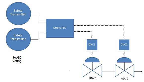
Figure 3 – SIF – SIL 3
.jpg)
Application Example
.jpg)
Figure 5 - Process with basic control
Figure 5 shows a simple process where a fluid is added in a continuous and automatic way to a process vessel. If the control system fails due to a very high pressure condition, a safety relief occurs, producing an undesirable smell out of the plant. Na acceptable risk rate for such event is 0.01/year or less (once every one hundred years or 1 change in 100 per year). Let’s specify a Safety Instrumented System (SIS) reaching such safety requirements.
In order to define the safety integrity requirements, the demand rate regarding the SIS should be estimated. In such example, the SIS demand rate should be the dangerous failure rate of the control loop.
The overall failure rate for the control loop may be estimated from the failure rates for components, which, in the example, we will assume as:
Failures/year
Pressure transmission 0.6
Controller 0.3
I/P 0.5
Control valve 0.2
Failure overall 1.6
The control loop for such example may fail in any direction, assuming that both are equally probable. Since the active control loop is under the operator supervision, it is assumed that only 1 failure out of 4 would be suddenly enough to cause a demand for a shut down condition without a previous intervention by the operator. That causes the overall result of (1 out of 2) x (1 out of 4) or 1/8 of overall failure rate, which should be used as the demand rate for a stop. Different assumptions should be made based on the specific knowledge on the equipment and conditions.
Therefore, the demand rate = 1.6/8 = 0.2/year
The acceptable unavailability =
.jpg)
The required availability is = 1-0.05 = 0.95
SIS with simple and direct connection is proposed to cut the supply when the system pressure reaches 80% of the safety valve setting value.
Compliance should be evaluated by the estimation of loop unavailability. Follows below the failure rates, showed as example and that could be consulted by each manufactured:
.jpg)
The loop is designed to fail in the safe direction, therefore, it is admitted that only 1 out of 3 failures would be in the unsafe direction. All those passive system failures would not be diagnosed.
Therefore, the non-diagnosed failures rate = 0.6/3 = 0.2/year
With a test annual frequency,
FDT = ½ fT = ½ x 0.2/year x 1 year = 0.1
That provides an availability of 0.9, which still does not comply with the safety requirements. However, the availability may be increase with a higher frequency of tests. With monthly tests we have,
FDT = ½ x 0.2/year x (1/12) year = 0.0083
Reaching an availability >0.99. The project test frequency should be specified as part of the project documents.
According to table 1, a SIL 1 system with frequent tests should provide an availability of 0.99 complying with the 95% availability required.
.jpg)
Table 1 - Architecture according to SIL level - IEC 61508
Some details
There is a wrong conception very common that the products by themselves or components are classified as SIL. Applicable products and components are at SIL levels, but they are not SIL individually. SIL levels are applied to the SIFs safety functions. The equipment or system should be used to support the risk reduction project. A piece of equipment certified for use in SIL 2 or 3 applications does not ensure, necessarily, that the system will meet SIL 2 or 3. All SIF components should be analyzed.
An important development parameter calculated during the SIL verification is the MTTFsp: Mean time between failures due to disturbances or false trips. Such variable indicates how many times the SIS may suffer a false trip until it reaches the shutdown condition. Table 2 below shows the estimation of cost by false trips in industries with different processes:
.jpg)
Table 2 - Costs with False Trips.
Conclusion
In practical terms, the aim is the reduction of failures and, consequently, the reduction of shutdowns and operational risks. The purpose is to increase the operational availability and also, in terms of processes, the minimization of variability with direct consequence to the profitability increase.
References
- IEC 61508 – Functional safety of electrical/electronic/programmable electronic safety-related systems.
- IEC 61511-1, clause 11, " Functional safety - Safety instrumented systems for the process industry sector - Part 1:Framework, definitions, system, hardware and software requirements", 2003-01
- ESTEVES, Marcello; RODRIGUEZ, João Aurélio V.; MACIEL, Marcos. Safety interlock system, 2003.
- http://www.exida.com/images/uploads/CCPS_LA_2010_SIS_EsparzaHochleitner.pdf
- William M. Goble, Harry Cheddie, "Safety Instrumented Systems Verification: Practical Probabilistic Calculation"
- Safety Instrumented Systems - César Cassiolato
- “Reliability in Measurement Systems and Safety Instrumented Systems” - César Cassiolato
- Manual LD400-SIS
- Safety Instrumented Systems – a practical view – Parte 1, César Cassiolato
- Researches on internet
Reliable Solutions

