DFI302
Foundation Fieldbus™ Universal Bridge
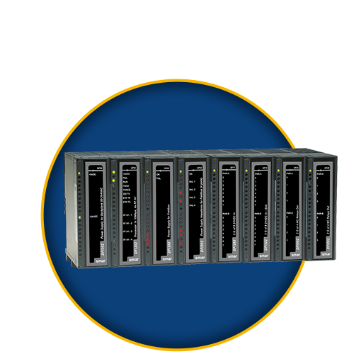
DFI302 is a key-interfacing element in the distributed architecture of field control systems. It combines powerful communication features with direct I/O access and advanced control for discrete and continuous applications. Due to its modular structure, it can be placed inside panels in the control room or sealed boxes in field. Highly expandable, it is targeted to applications ranging from small standalone systems to large and complex plants.
O DFI302 is a modular multifunctional device with a DIN-rail mounted backplane into which all components are installed, including main and fieldbus power supplies (DF50 and DF52, respectively), controllers (DF63, DF73, DF95 and DF97), and line impedance (DF53) modules. They are plugged-in through industrial grade connectors and by using a robust metal screw. A conventional I/O subsystem with modules for analog and discrete inputs and outputs can be connected (optional). Modularity is the keyword for DFI302 flexibility. Besides, since all modules including the fieldbus power supply subsystem are plugged into the same backplane, the DFI302 comes up as a single integrated unit.
For further information about the DFI302 automation platform more quickly, the user manual can be obtained separately by subjects. Are they:
A - Installation and Basic Configuration
This part has all general and basic information about installation of controllers, racks, I/O modules, IP configuration, OPC servers, firmware update, project types, and general information about adding function blocks and flexible function blocks.
This part also has troubleshooting information, and the SRF (Service Request Form).
It has the following sections:
- Overview
- Installing
- Setting up
- Configuring the OPC servers
- Configuring strategies
- Adding function blocks
- Adding logic by using flexible function blocks
- Adding I/O modules
- Adding racks
- Troubleshooting
- Appendix (SRF)
B - Technical Specifications
This part has all technical specification of the DFI302 hardware components. They are:
- Controllers – DF63, DF73, DF75, DF89, DF95, DF97 and DF100.
- Ethernet cables, serial cables and cables for racks’ interconnection
- Power supplies – DF50, DF53/DF98, DF52/60, and DF56.
- Interfaces – DF58 and DF61
It has the following sections:
- Technical specification for controllers
- Cable specification
- Adding power supplies
- Adding interfaces
C - Modbus
This part has information to integrate systems that use Modbus protocol to the DFI302 automation platform. It has the following section:
- Adding Modbus
D - Configuring Strategies with HSE/FF Controllers
This part has information to create control strategies that use the DF63 as a controller. It has the following section:
- Creating a FOUNDATION fieldbus strategy by using the DF63
E - Configuring Strategies with HSE/PROFIBUS Controllers
This part has information to create control strategies that use the DF73, DF95 or DF97 controllers.
- The DF73 is the HSE/Profibus-DP controller with 2 Ethernet 100 Mbps ports, and 1 Profibus DP channel.
- The DF95 is the HSE/Profibus controller with 2 Ethernet 100 Mbps ports, 1 serial port, 2 Profibus PA ports, and 1 Profibus DP channel.
- The DF97 is the HSE/Profibus controller with 2 Ethernet 100 Mbps ports, 1 serial port, 4 Profibus PA ports, and 1 Profibus DP channel.
It has the following section:
F - Configuring Strategies with HSE/Modbus Controllers
This part has information to create control strategies that use the DF89 controller.
The DF89 is the HSE/Modbus controller with 2 Ethernet 100 Mbps ports and 1 RS-485/RS-232 Modbus RTU port.
It has the following section:
- Creating a Modbus configuration by using the DF89
G - Configuring Strategies with HSE/WirelessHART Controllers
This part has information to create control strategies that use the DF100 controller.
The DF100 is the HSE/WirelessHART™ controller with 2 Ethernet 100 Mbps ports, 1 RS-485 port and 1 WirelessHART channel.
It has the following section:
- Creating a FOUNDATION fieldbus strategy by using the DF100
H - Redundancy
To meet the requirements for fault tolerance, system availability and safety of the industrial process, the DFI302 HSE controllers (DF63/DF73/DF75/DF89/DF95/DF97) work with a Hot Standby redundancy strategy.
This part has information about installation and configuration of redundant systems which use those controllers.
It has the following sections:
- Adding redundancy to DFI302 HSE controllers
- Adding redundancy with redundant I/O modules R-Series
I - Conventional and Redundant Input/Output Modules
There are many types of input/output modules available for DFI302 automation platform, designed to fit a broad range of applications in the automation and process control industry.
The available types are:
- Discrete inputs and outputs
- Combined discrete inputs and outputs
- Pulse inputs
- Analog inputs and outputs
- HART inputs and outputs
- Redundant inputs and outputs
The Digital and Analog Input/Output Modules of DFI302 manual has all information about those modules.
J - Interfaces for Panels
With the Smar’s panel interfaces is possible to eliminate the hard work of making cables, fixing washers and mounting terminal blocks. Just fit the interfaces in the DIN rail and connect the cable. It’s easy and fast!
The interfaces have many features which will fit your application. They were designed for the Smar’s I/O modules.
The Interfaces for Panels manual has all necessary information. This part of manual can be obtained on the Smar’s website (www.smar.com), downloading the file:
Controllers
|
Controller with FOUNDATION FieldbusTM Linking Device function |
|
|
HSE/PROFIBUS-DP Controller |
|
|
High Speed Ethernet Controller |
|
| DF89 | Modbus/HSE Controller |
| DF95 | HSE/PROFIBUS 1 DP and 2 PA controller |
| DF97 | HSE/PROFIBUS 1 DP and 4 PA controller |
| DF100 | HSE/WirelessHART™ controller |
I/O Modules
|
DC Input |
DF11 |
2 Groups of 8 24VDC Inputs (Isolated) |
|
DF12 |
2 Groups of 8 48VDC Inputs (Isolated) |
|
|
DF13 |
2 Groups of 8 60VDC Inputs (Isolated) |
|
|
DF14 |
2 Groups of 8 125VDC Inputs (Isolated) |
|
|
DF15 |
2 Groups of 8 24VDC Inputs (Sink) (Isolated) |
|
|
AC Input |
DF16 |
2 Groups of 4 120VAC Inputs (isolated) |
|
DF17 |
2 Groups of 4 240VAC Inputs (isolated) |
|
|
DF18 |
2 Groups of 8 120VAC Inputs (isolated) |
|
|
DF19 |
2 Groups of 8 240VAC Inputs (isolated) |
|
|
Switch |
DF20 |
1 Group of 8 On/Off Switches |
|
DC Output |
DF21 |
1 Group of 16 Open Collector Outputs |
|
DF22 |
2 Groups of 8 Transistor (source) Outputs - Isolated |
|
|
AC Output |
DF23 |
2 Isolated Groups of 4 120/240VAC Outputs |
|
DF24 |
2 Isolated Groups of 8 120/240VAC Outputs |
|
|
AC/DC Output |
DF25 |
2 Groups of 4 NO Relays Outputs |
|
DF26 |
2 Groups of 4 NC Relays Outputs |
|
|
DE27 |
1 Group of 4 NO and 1 Group of 4NC Relay Outputs |
|
|
DF28 |
2 Groups of 8 NO Relay Outputs |
|
|
DF29 |
2 Groups of 4 NO Relay Outputs |
|
|
DF30 |
2 Groups of 4 NC Relay Outputs |
|
|
DF31 |
1 Group of 4 NO and 4NC Relay Outputs (Without RC protection) |
|
|
DF69 |
2 Groups of 8 NO Relay Outputs (With RC protection) |
|
|
DF71 |
2 Groups of 4 NO Relays Outputs (Without RC protection) – Max 10 mA |
|
|
DF72 |
2 Groups of 4 NC Relays Outputs (Without RC protection) – Max 10 mA |
|
|
Analog Input |
DF44 |
1 Group of 8 Voltage/Current Analog Inputs with Internal Shunt Resistors |
|
DF45 |
1 Group of 8 Low Signal Analog Inputs for TC, RTD, mV and Ohm |
|
|
DF57 |
1 Group of 8 Voltage/Current Differential Analog Inputs with Internal Shunt Resistors) |
|
|
Analog Output |
DF46 |
1 Group of 4 Voltage/Current Analog Outputs |
|
DC Input and AC/DC Output |
DF32 |
1 Group of 8 24VDC Inputs and 1 Group of 4 NO Relays (Isolated) |
|
DF33 |
1 Group of 8 48VDC Inputs and 1 Group of 4 NO Relays (Isolated) |
|
|
DF34 |
1 Group of 8 60VDC Inputs and 1 Group of 4 NO Relays (Isolated) |
|
|
DF35 |
1 Group of 8 24VDC Inputs and 1 Group of 4 NC Relays (Isolated) |
|
|
DF36 |
1 Group of 8 48VDC Inputs and 1 Group of 4 NC Relays (Isolated) |
|
|
DF37 |
1 Group of 8 60VDC Inputs and 1 Group of 4 NC Relays (Isolated) |
|
|
DF38 |
1 Group of 8 24VDC Inputs and 1 Group of 2 NO and 2NC Relays (Isolated) |
|
|
DF39 |
1 Group of 8 48VDC Inputs and 1 Group of 2 NO and 2 NC Relays (Isolated) |
|
|
DF40 |
1 Group of 8 60VDC Inputs and 1 Group of 2 NO and 2 NC Relays (Isolated) |
|
|
Pulse Input |
DF41 |
2 Groups of 8 Low Frequency (0 - 100Hz) 24VDC Pulse Inputs |
|
DF42 |
2 Groups of 8 High Frequency (0 - 10KHz) 24VDC Pulse Inputs |
|
|
DF67 |
2 Groups of 8 High Frequency (0 - 10 KHz) AC Pulse Inputs |
|
|
DF77 |
Module with 5x2 Pulse inputs with tester rack (HFC302) |
Interfaces
|
DF58 |
EIA 232 / 485 interface |
Power Supply
|
Power Supply for Backplane 90 – 264 Vac |
|
|
H1 Foundation Fieldbus & Profibus PA Power Supply (Uin = 90-264 Vac / 20-30 Vdc) |
|
|
Power supply for backplane with redundancy capability |
|
| DF87 | Power Supply for Backplane 20-30 Vdc, 5 A, redundant, with diagnostic |
Power Supply Impedance
|
Power Supply Impedance for Fieldbus |
Accessories
|
Rack |
DF1A |
Shielded rack with 4 slots |
| DF92 | Rack with 4 slots for redundant CPUs, hot swap and diagnostic support |
|
| DF93 | Rack with 4 slots, with diagnostic | |
| Cables |
DF54 |
Cable 100 Base-TX |
|
DF55 |
Cable 100 Base-TX – cross cable |
|
|
DF59 |
Cable RJ12 used to connect DF51 and DF58 |
|
|
DF68 |
Cable to connect DFI302 to LC700's CPU |
|
|
DF76 |
Cable to connect co-processors |
|
|
DF82 |
Cable to connect redundant controllers - length 500 mm |
|
|
DF83 |
Cable to connect redundant controllers - length 1800 mm |
|
| DF90 | IMB power cable | |
| DF91 | Lateral Adapter | |
|
Flat Cables |
DF101 | Flat cable to connect racks by left side – length 70 cm |
|
DF3 |
Flat Cable to Connect Two Racks - Length 65mm |
|
|
DF4A |
Flat Cable to Connect Two Racks (Shielded) - Length 0.65 m |
|
|
DF5A |
Flat Cable to Connect Two Racks (Shielded) - Length 0.81 m |
|
|
DF6A |
Flat Cable to Connect Two Racks (Shielded) - Length 0.98 m |
|
|
DF7A |
Flat Cable to Connect Two Racks (Shielded) - Length 1.1 m |
|
| DF102 | Flat cable to connect racks by right side - length 65 cm | |
| DF103 | Flat cable to connect racks by right side - length 81 cm | |
| DF104 | Flat cable to connect racks by right side - length 98 cm | |
| DF105 | Flat cable to connect racks by right side - length 115 cm | |
|
Terminator |
DF2 | Rack Terminator |
| DF96 |
Terminator for the last rack - left side |
|
|
Empty module |
DF0 |
Blind Module to fill empty slots |
| IMB Soft Starter |
DF84 |
IMB Soft Starter |
|
Support for single module |
DF9 |
Support for a single module |
R-Series
|
Racks and Acesssories |
DF106 |
Master Rack - 6 slots for IO redundancy |
|
DF110 (1) |
Slave Rack - 10 slots for IO redundancy - Terminal blocks |
|
|
DF110 (2) |
Slave Rack - 10 slots for IO redundancy - Interface cabling |
|
|
DF109 |
Thin stub cable (0,40m) |
|
|
DF119 |
Thick cable (1,0m) for DF106-DF109 or DF106-DF110 |
|
|
Scanners |
DF107 |
Master Scanner for IO Redundancy |
|
DF108 |
Slave Scanner for IO Redundancy |
|
|
I/O Modules |
DF111 | 1 Group of 16 Redundant Digital Inputs 24 Vdc - Source |
| DF112 | 1 Group of 16 Redundant Digital Outputs 24 Vdc - Sink | |
| DF113 | 1 Group of 8 Redundant Current Analog Inputs | |
|
DF114 |
1 Group of 8 Redundant Current Analog Outputs |
|
|
Complement |
ITF-CR-10 | Interface cabling ( 1m to 5 m) |
| ITF-CR-15 | ||
| ITF-CR-20 | ||
| ITF-CR-25 | ||
| ITF-CR-30 | ||
| ITF-CR-35 | ||
| ITF-CR-40 | ||
| ITF-CR-45 | ||
| ITF-CR-50 | ||
| ITF-DIG |
Passive Interface Panel for 16 Digital Input and/or Output Module - DC |
|
| ITF-AN-IOR |
Interface Panel for 8 Analog Input and/or Output Module |
Download Area
Manuals
Firmware
Catalogs
Certificates
Data Sheets
Reliable Solutions

