
Flow Measurement

1. Introduction
Flow is the third most measured magnitude in industrial processes. It encompasses a wide range of applications from simple ones, like water flow in treatment stations and households, until industrial gases and fuel measurement, in addition to more complex ones. The right choice of a given device in flow measurement depends on many factors. Among them, enhanced are:
- exactness in measurement
- type of fluid: liquid or gas, clean or polluted, number of steps, electric conductivity, transparence, etc.
- thermodynamic conditions: for example, pressure and temperature levels to be measured
- physical space available costs, etc.
- Currently the fluid meters (liquid, gas and steam) are very important in a process, as they are used to determine the quantity of products sold, bought and transferred between manufacturers, transporters and end consumers.
Pressure Temperature Flow Level Conductivity pH Oxygen Density Others
.jpg)
Figure 1 – Process Variables
Fluid flow measuring has always been present in our day-to-day work. For example, the residence water meter, the display of a vehicle fuel pump, etc.
In History, great names inscribed their contributions. In 1502 Leonardo de Vinci observed that the quantity of water per time unit flowing in a river was the same anywhere, regardless of width, depth, inclination etc. But the development of practical devices was only possible with the Industrial Age and the work of researchers like Bernoulli, Pitot and others.
Let´s examine initially some concepts for better understanding flow measurement.
2. How to define flow
Flow can be defined as the volume or mass quantity of a fluid that flows through the section of a pipe of channel per time unit.
- Volume Flow– It is defined as the volume quantity that flows through a given section at a considered time interval. The most common volume units are:m3/s, m3/h, l/h, l/min, GPM (gallons per minute), Nm3/h (normal cubic meter per hour), SCFH (normal cubic foot per hour), among others.
.jpg)
, where: V = volume, t = time, Q = volume flow.
- Mass flow– It is defined as the mass quantity of a fluid that flows through a given section at a considered time interval. The most used mass flow units are: kg/s, kg/h, t/h, lb/h.
.jpg)
, where: m = mass , t = time, Qm = mass flow.
2.1. Physical concepts on flow measurement
Flow measurement requires reviewing some concepts related to fluids, as flow is generally influenced by them. The main concepts are:
- Specific heat
Specific heat is defined as the quotient of the infinitesimal quantity of heat supplied to a substance mass unit by the infinitesimal temperature variation resulting from this heat.
In practice, we have: the heat quantity required to change the temperature of 1 g of a substance into 1ºC.
- Viscosity
It is defined as the resistance opposed to a liquid flow in a given pipe. This resistance will cause a loss of additional load that should be considered in the flow being measured.
- Number of Reynolds
Non-dimensional number used to determine if the flow is processed in laminar or turbulent regime. It is important to determine it as the parameter modifying the load coefficient.
.jpg)
Where:
v – velocity (m/s)
D – pipe diameter (m)
ν - cinematic viscosity (m2/s)
Note:
- In practice, if Re > 2,320, the flow is turbulent, otherwise it is always laminar.
- In industrial flow measurement, the outflow regime is turbulent with Re > 5.000, in most cases.
Velocity Distribution in a Pipe
- If the outflow is processed inside a pipe, the velocity will vary: it will be maximum at the center and minimum at the pipe wall.
Laminar Regime
- It is characterized by its more accentuated velocity profile, where the differences are greater.
.jpg)
Figure 2: Velocity profiles in laminar regime.
- Turbulent Regime
Characterized by a velocity profile more uniform than the laminar profile, its velocity differences are smaller.
.jpg)
Figure 3: Velocity Profile in turbulent regime
3. Types of Flow Meters
Flow meters can be classified according to the chart below:

Figure 4 – Flow measurement classification
3.1. Flow Calculation Equations
Flow calculation equations can be obtained generically for the three types of meters presented. The Mass Conservation Equation is applicable, as well as the Energy Conservation Equation, the latter in its simplified form, which is the Bernoulli Equation. Therefore, it is the ideal drainage mode through an area reduction and taking a current line between points 1 and 2, as shown on figure 5.
.jpg)
Figure 5 – Bottle neck drainage
The Bernoulli equation applied to the ideal drainage, between points 1 and 2 on the figure results in the following equation:
.jpg)
whose first term represents the kinetic energy, the second term the pressure energy resulted from the drain work, while the third term represents the potential energy. There are identical parcels for point 2 on the right side. This equality means that the total of the three parcels is a constant throughout the current line, without friction losses. For horizontal drainage, there is no potential variation, being z1 = z2. Using the mass conservation equation between section 1 and 2 for incompressible drainage, we have:
.jpg)
Being A the area of the transversal area and β the ratio between the meter and the piping meters, β = D2/D1 (or d/D, according to the notation), one of the equation (1) velocities can be isolated, resulting the following equation:
.jpg)
The flow can then obtained by multiplying this velocity by the respective area, equation (4). In this case, the flow is an idel flow, as it was obtained through the Bernoulli equation for the ideal drainage.

If we take the most extreme case, whose point 2 is located over the vena contracta, there can be defined a contraction coefficient for the main vein, which is the ration between the vena contract A2 area and the meter passage area, Am. Hence:

The real flow can be obtained by multiplying the ideal flow by a coefficient of correction Cv. This coefficient includes the corrections related to loss of energy between points 1 and 2, between which the pressure differential is obtained. This differential partly comes from the drainage accelaration and partly from the loss of load. The latter always acts aiming at increasing the differential, reason why the Cv value is always inferior to that of the unit. So, taking into account these correction and the Am meter area, the equation for the flow is given by:
.jpg)
The Cc coefficient differs from the unit only on the orifice plate, when the pressure sockets are not on the corner taps. The vena contracta exists in this type of socket, but the pressure is being read on the plate, so that area A2 can be considered as the Am orifice area. In function of the difficulty to determine all coefficients on the equation (6), the practice is to ignore the very Cc and introduce the C and K coefficients, so that this equation takes up the following forms:
.jpg)
3.2. Pressure Differential Meters
The work principle is based on the change of the drainage area, through the reduction of the diameter or the use of an obstacle, or still through the change of the drainage direction. These changes on area or direction cause a local drainage acceleration that alters the velocity and consequently the local pressure. Pressure variation is proportional do the flow square. These are well-known, normatized, low-cost meters. It is estimated that they account for 50% of the devices used on liquid measurement.
They are made up by a primary and a secondary element. The primary element is associated to the piping and interferes with the drainage by supplying the pressure differential. The secondary element is responsible for reading this differential and can be a simple liquid column manometer, in its different versions, or even a more complex transducer, with acquisition and electronic treatment of the pressure value read.
3.3. Flow measurement market technologies
There are multiple flow measurement technologies on the market, but undoubtedly the orifice plate meter is the most used, due to its low cost combined with the large amount of information cumulated along decades of application. This means, among other reason, that is easy for every automation technician on Process Control may eventually encounter with this type of meter. So, It is convenient for them to know its basic work principles. Furthermore, through many decades the orifice plate meter has been improved to increase its range, precision and robustness. Several practical and academic works are available as a resource for professionals who want to apply this type of meter. See figures 6 and 7, which compare the different existing types of meters.
.jpg)
Figure 6 – Comparison between different fluid meters
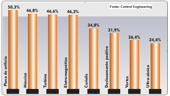
Figure 7 – Most used flow meters
4. Differential Pressure Transmitter
4.1. LD400 Work Principle
SMAR LD400 Series Transmitters is based on capacitive sensors where the pressure applied to sensors diaphragms produces a capacitance variation between them and a central diaphragm. This variation is used to vary the frequency of an oscillator that is measured directly by the CPU and converted into pressure. There is no A/D conversion and this contributes for the exactness of analog/digital conversions and for eliminating built-in drifts. SMAR masters digital reading since the 80s.
Capacitive sensors are very reliable devices that have linear responses and are practically insensitive to temperature variations. They are recommended for instrumentation and process control, as their performance on temperature and static pressure are excellent.
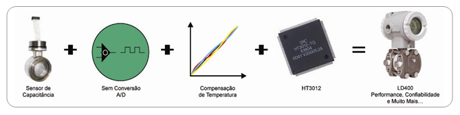
Figure 8 – LD400 Functional Diagram
4.2. LD400 Characteristics and Benefits
- The LD400 line has 2 exactness class:
- Standard Model: Exactness of 0.06%
- High Performance Model: Exactness of 0.045%
- Ideal for flow measurement applications
- Minimizes the Probable Total Error and consequently process variability
- Ideal for applications on SIL2 and SIL3 safety systems
- Its linear response enables high, exact rangeability
- Rangeability of 200:1
- Response time of 35 ms (the market fastest digital transmitter )
- Guarantee of stability of ± 0.2% of URL for 12 years (high performance model)
- Built-in transient suppressor and anti-surge features
- Bi-directional, persistence totals
- Power supply without polarity (12 to 50 Vcc) – prevents connection errors and short circuits
- Multifunctional display
- 16-bit CPU, ensuring high performance
- High performance mathematical co-processor that guarantees the transmitter superior work
- Housing with electrical connection inputs on the lower part and resin terminal block – anti- corrosion protection and low isolation
- Sealed housing for custody and fiscal transference
- Local adjustment via HALL sensor
- Simplified local adjustment tree
- Writing protection jumper
- Possibility of firmware update via flash memory
- Rupture pressure limit of 10000 psi
- Advanced diagnostics: indication of open and short-circuited sensor, sensor failure in any chamber, disconnected sensor, overpressure beyond the acquisition limit, indication of a number of diagnostics on the display, maximum and minimum temperature, zero deviation, etc.
- Micro-processed pressure transmitters have the great advantage of allowing better user interaction with friendly interfaces. In addition, their self-diagnostics features make it easier to identify problems. With the advent of fieldbus networks it is now possible to benefit the most from digital technology. These transmitters provide better exactness, electronic stability superior to the analog models, besides facilitating adjustments and calibrations. The digital technology also permits the implementation of powerful algorithms to improve measurement performance and exactness and online monitoring the equipment life.
4.3. How to specify Pressure Transmitters
Incomplete specification or even inconsistent data are fairly common in the documentation to acquire pressure transmitters. At a first glance they look like simple project items, but there are many details that, if not correctly specified, ma y harm the mounting or even the operation, and the loss can be bigger than the equipment cost. The present topic tries to clarify some fundamental questions in the process of specifying pressure transmitters. It is worth remembering how important is getting to know the following subjects:
- pressure measurement physical principles;
- types of measurable pressures;
- sensors and their work;
- industrial instrumentation;
- installation and maintenance and operation care;
- main applications.
What is being measured?
- Manometric pressure;
- Absolute pressure;
- Differential pressure;
- Other magnitudes inferred from pressure measuring ( flow, level, volume, force, density, etc).
It should be noted that pressure measurements below the atmospheric type do not necessarily need absolute pressure transmitters. Absolute pressure transmitters are recommended only to avoid the influence from the variations on the atmospheric pressure. This influence will only be critical when measuring levels very close to the atmospheric pressure (above or below). Wherever else, manometric pressure transmitters can be used normally.
Why measuring pressure?
Generally, pressure is measured for:
- Process control or monitoring;
- Protection (safety);
- Quality control;
- Commercial fluid transactions (custody transference, fiscal measurement);
- Studies and research;
- Mass and energy balance.
- Rupture pressure limit of 10000 psi
- Advanced diagnostics: indication of open and short-circuited sensor, sensor failure in any chamber, disconnected sensor, overpressure beyond the acquisition limit, indication of a number of diagnostics on the display, maximum and minimum temperature, zero deviation, etc.
- Micro-processed pressure transmitters have the great advantage of allowing better user interaction with friendly interfaces. In addition, their self-diagnostics features make it easier to identify problems. With the advent of fieldbus networks it is now possible to benefit the most from digital technology. These transmitters provide better exactness, electronic stability superior to the analog models, besides facilitating adjustments and calibrations. The digital technology also permits the implementation of powerful algorithms to improve measurement performance and exactness and online monitoring the equipment life.
- Ideal for applications on SIL2 and SIL3 safety systems
- Its linear response enables high, exact rangeability
- Rangeability of 200:1
- Response time of 35 ms (the market fastest digital transmitter )
- Guarantee of stability of ± 0.2% of URL for 12 years (high performance model)
- Built-in transient suppressor and anti-surge features
- Bi-directional, persistence totals
- Power supply without polarity (12 to 50 Vcc) – prevents connection errors and short circuits
- Multifunctional display
- 16-bit CPU, ensuring high performance
These objectives must be considered when choosing the equipment. More important issues on performance such as: exactness, overpressure and static pressure limits, stability and otherare liable to unnecessarily increase the cost of the project.
Most manufacturers offer the market more than one version of transmitters with different technical features and different prices.
Which is the process fluid?
The supplier must be informed about the fluid requirements. Generally the maker may recommend special materials or connections. Note that the final decision will be always a user´s call or taken by the engineering firm involved. Some process fluid data are fundamental on the transmitter choice:
- State (liquid, gas, steam) → Defines the valve drain/vent position;
- Maximum process pressure → Important to evaluate the transmitter overpressure and static pressure limits;
- Maximum process temperature → It may be determinant for using remote seals or only keep a minimum distance from the impulse line (piping).
Optionals?
Some optional features can be included in the transmitter supply:
- Local indicator: this item is not too costly and is very useful, as it not only allows the reading of variables in engineering units (kgf/cm2, bar, mmH2O, Pa, psi, etc.) but also facilitates configuring the transmitter when a configurator is not available.
- Manifold: product bundling ( transmitter + manifold purchase) has commercial advantages and avoids technical incompatibilities on mounting.
- Support for 2” pipe: an almost compulsory item. Some supports also allow mounting on flat surfaces. At least stainless steel nuts and bolds should be specified, for better resistance to corrosive atmospheres.
- Cable clamps: this item can be ordered with the transmitter. However, it should be included on the mounting material, in order to ensure the compatibility with the gauge of the specified cable.
Communication protocol?
The most common communication protocols are:
- 4-20 mA + HART,
- Foundation Fieldbus
- Profibus PA.
Some manufacturers offer transmitters that change their protocol version by simply substituting the electronic circuit board or just the firmware, enabling them for use with different systems. Also, they offer with the transmitters, CDs with all the archives (DDs and DTMs) that ensure communication and interoperability with the several existing control systems.
Special tools?
Transmitters with Foundation Fieldbus or Profibus PA protocols do not require portable configurators, since the network configuration tools installed on supervising computers or any engineering station are also capable of accessing and configuring the devices. For conventional projects (4-2-mA + HART), are recommended hand-held configurators. In some transmitters, the configuration can be done directly on the devices, with the use of resources like the magnetic screwdriver or local button pads.
Pre-configuration?
On conventional transmitters it is possible to order, generally at no additional cost, some pre-configurations:
- square root extraction;
- calibrated range;
- display indication in engineering units (pressure);
- display indication in special units, for example: m3/h, l/h, m3. In this case, the unit and scale should be indicated previously.
Certifications?
It is common for the user to request to the manufacturer calibration certificates issued by metrology laboratory tracked by RBC. Standardized certificates are generated and issued during the device production stage. Other calibration certificates, when issued by RBC-tracked labs may require longer delivery terms and involve additional costs.
Another important certification must be observed when the transmitters are used in hazardous areas. The projects for these cases adopt regulations compliant to explosion proof, increased safety or intrinsic safety.
The certificates are distinct ones and the user is responsible for its correct utilization.
The same applies to SIS, Safety Instrumented Systems. A pressure transmitter specified for critical areas, namely, for safety functions, it is an equipment with the probability of low occurrence of failures and high operation reliability. There are two concepts in the market. One, based on the “Prove in Use” concept and another based on the IEC 61508 certification. In practice, there are many applications specified for equipment with SIL certification to be used on control systems without the safety function. Also there has been a great deal of misinformation conducive to the purchase of more expensive equipment, where the SIL specification is not necessarily useful and make the use and operation of the equipment more difficult.
Safety Instrumented Systems (SIS) are designed for operational safety and ensure emergency shutdowns within the limits considered to be safe, whenever the operation goes beyond these limits. The main goal is to avoid accidents inside and outside the factories, such as fires, explosions, damage to the equipment, protection to the production and the property and, moreover, avoid risks to life, damage to the health of persons and catastrophic impact on the community.
No equipment is totally immune to failures and must always deal basically with 3 types of failures: random hardware failures, system failures and common-cause failures.
What should the user know about SIL-certified transmitters and why they are not the best choice for control and monitoring?
- No change of configuration, simulation, multi-drop or loop test can be made with the equipment in normal operation, namely, requiring safety. In these conditions, the output cannot be evaluated safely. In other words, a HART/4-20mA equipment with SIL2 certification will not have SIL level if the HART communication is enabled and enabling writing.
- In safe condition it must be with write protection disabled;
- No local adjustment can be executed (i.e., the local adjustment must be disabled);
- Nothing is entirely safe. The goal is to reduce the possibility of failures occurring;
- In case of failure, this must be fail safe, i.e., capable of being identified and allow corrective measures.
Special connections?
In applications with aggressive fluids, high temperature or viscosity, suspended solids, integral transmitters with remote seal (called level transmitters) are recommended.
Whenever possible, the use of seals must be avoided, as these degrade the measurement exactness, increase the transmitter response time and suffer great influence from the ambient temperature. The calibration of transmitters with remote seals require special care, as both the transmitter position and the filling fluid density are factors to be considered.
Seals with flanged connections must be compatible with the process flanges and respect the pressure classes established on the pressure and temperature tables of the respective standards.
Pressure range / rangeability?
The manufacturers adopt a standardized terminology that must be learned:
- URL → calibration range upper limit;
- LRL→calibration range lower limit, generally LRL = -URL;
- URV→calibration range upper value (should be smaller than or equal to the URL);
- LRV→calibration range lower value (should be higher than or equal to the LRL);
- SPAN→ URV – LRV (should be higher than the device minimum SPAN).
The ratio URL / minimum SPAN defines the device rangeability. The factory catalogs generally show the URL , LRL values and the minimum SPAN for the several ranges of transmitters. The minimum SPAN of a given band will always be higher than the URF or the immediately lower range.
- Ideal for applications on SIL2 and SIL3 safety systems
- Its linear response enables high, exact rangeability
- Rangeability of 200:1
- Response time of 35 ms (the market fastest digital transmitter )
- Guarantee of stability of ± 0.2% of URL for 12 years (high performance model)
- Built-in transient suppressor and anti-surge features
- Bi-directional, persistence totals
- Power supply without polarity (12 to 50 Vcc) – prevents connection errors and short circuits
- Multifunctional display
- 16-bit CPU, ensuring high performance
For example:
Range 4 → URL: 25 kgf/cm2; minimum Span : 0,21 kgf/cm2; overpressure or static pressure limits: 160 kgf/cm2;
Range 5 → URL : 250 kgf/cm2; minimum Span : 0,21 kgf/cm2; overpressure or static pressure limits: 320 kgf/cm2.
For an application with calibrated range of 0 to 20 kgf/c m 2 range 4 or even range 5 can be used. However, the lower range should always be chosen. All specs for stability, temperature effect, static pressure effect are determined with URL percent values. An exception for that choice is when the overpressure or static pressure limits can be reached. On the example above, this limit is of 160 kgf/cm2 for range 4 and 320 kgf/cm2 for range 5.
Functional resources
Some transmitters have very interesting functional resources. For transmitters with Foundation Fieldbus protocol it is important to know the functional block library available. The user must be informed not only about the diversity of these blocks, but also about the marketing policy for these resources. Some manufacturers supply the device with some basic blocks and charge extra price to include advanced blocks. It is also important to be aware of the number of blocks that can be processed on a single transmitter. This limit can be critical in projects with more complex control loops.
For conventional 4-20 mA + HART transmitters the use of additional functionalities is also possible.
PID control
In this configuration the transmitter executes de PID algorithm, comparing the process variable with a pre-adjusted set-point and generates the current output signal for direct connection to the control valve positioner. This resource is valid for simple control loops not needing operator intervention (always working on automatic with constant set-point).
Flow total
The differential pressure transmitter when used on flow measurements can be configured for local indication of the total flow, besides the instantaneous.
.jpg)
Figure 9 – Bock diagram and 4-20mA+HART pressure transmitter functions
Static performance or exactness of a pressure transmitter (often confounded with precision, when exactness is associated with the proximity of the true value and precision to the dispersion of the values resulting from a series of measures) depends on how well the transmitter is calibrated and how long it can keep its calibration.
The calibration of a pressure transmitter involves zero adjustment and span. Exactness normally includes effects of non-linearity, hysteresis and repeatability.
Normally exactness is supplied in % of the span calibrated.
5. Examples of flow measurement with the differential pressure transmitter
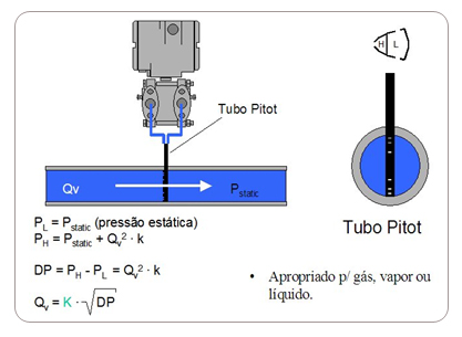
Figure 10 –Pitot tube Flow measurement
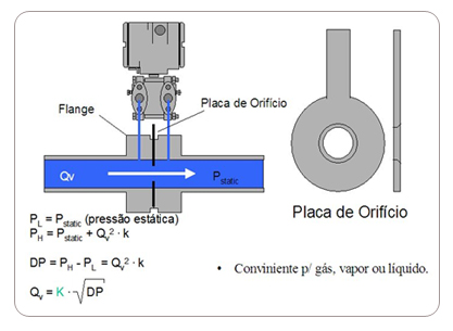
Figure 11 – Orifice plate flow measurement
6. Curiosity: The world pressure transmitter market
In today´s industrial processes and controls we have witnessed the technological advancement brought by the advent of micro-processers and electronic components, the Fieldbus technology, the Internet, etc, everything making the operations easier, ensuring process optimization and performance and operational safety. This advancement allows that pressure transmitters, as well as those of other types, may be projected to ensure high performance in measurements that so far only use analog technology. The existing analog transmitters were developed with discrete component, subject to drifts due to the temperature, environment and process conditions, with constant adjustments through potentiometers and switches. The digital technology also brought simplicity of use.
Pressure transmitters are widely used on processes and applications with several functionalities and figure 1 shows that most industrial processes involve flow measurement.
According to ARC Advisory Group, the world pressure transmitter market in 2006 accounted for 2,38 billion dollars and has an estimate of 2,8 billion for 2013.
Also worth mentioning are the transmitters for SIS - Safety Instrument Systems applications, in addition to the wireless transmitters that begin to be used on some applications.
SMAR is finishing the development of its WirelessHART and ISA-SP100 pressure transmitters, soon to be introduced to the market.
For SIS applications, SMAR already offers its LD400-HART-SIS transmitters. For details, consult: https://www.smar.com.br/public/img/produtos/arquivos/ld400ce.pdf
7. Conclusion
This article presented a little of the flow measurement history, its importance in process automation and control, peculiarities and characteristics, combined with the technological advancement of flow transmitters. We also examined the market and its growth trend and the care related to installations, the specifications and terminology adopted for transmitters.
8. References
- Controle&Instrumentação Magazine Issue 138, Flow Measurement, 2008, César Cassiolato and Evaristo O. Alves.
- Controle&Instrumentação Mag Issue 93, Pressure Transmiters, 2004, César Cassiolato.
- Controle&Instrumentação Mag Issue 106, Brazil breaks technological barriers with innovation– Pressure Transmitters, César Cassiolato.
- Intech Issue 74 , Pressure Transmitters: sensores, trends, market and applications, César Cassiolato, 2005
- Especifying Pressure Transmitters, César Cassiolato and Francisco Julião, 2006.
- Controle&Instrumentação Mag 113, Some important concepts in Pressure Transmitters, 2006, César Cassiolato.
- Intech Mag Issue 93 , Pressure Measurement -Tutorial, 2007
- Controle&Instrumentação Edição 135, Pressure Measurement: everything you must know, 2008, César Cassiolato.
- Operation and Training Manuals for SMAR LD301, LD302 , LD303 e LD400 pressure transmitters
- Pressure Transmiters Presentations, César Cassiolato, Evaristo O. Alves, 2001-2008.
- Mecatrônica Atual Mag - Flow Measurement, Rogério Souza da Mata, Edição 26, 2006.
- Technical Articles – César Cassiolato
- https://www.smar.com/en/technical-articles
- https://www.smar.com/en
Related Links:
- Consult SMAR technical articles list: www.smar.com/en/technical-articles
- PROFIBUS: https://www.smar.com/en/technical-articles-profibus
Reliable Solutions

