
Inductive Coupling and how to Minimize their Effects in Industrial Installations
|
|

Introduction
The coexistence of equipment of different technologies and the inadequacy of the installations favors the emission of electro-magnetic energy and often causes problems of electro-magnetic compatibility.
EMI is the energy that causes undesirable response to any equipment and may be generated by sparking on the motor brushes, tension circuits switching, activation of inductive and resistive loads, activation of switches, circuit breakers, fluorescent bulbs, heaters, automotive ignitions, atmospheric discharges and even the electrostatic discharge between persons and equipment, microwaves devices, mobile communication equipment etc. All this may provoke alterations with the resulting overload, sub-voltage, peaks, voltage transients etc., which may cause high impact on a communication network. This is very common in industries and factories, where EMI is fairly frequent in function of the larger use of machines such as welding instruments, motors (MCCs) and in digital networks and computers in the vicinity of these areas.
The biggest problem caused by EMI is the occasional situations that slowly degrade the equipment and its components. Many different problems may be generated by EMI on electronic equipment as communication failures between devices of the same equipment network and/or computers, alarms produced without explanation, action on relays that do not follow logic, without being commanded, in addition to the burning of electronic components and circuits etc. It is very common the occurrence of noises in power source lines due to bad grounding and shielding or even error in the project.
The topology and the distribution of the wiring, types of cables, proctection techniques are factors that must be considered to minimize the EMI effects. Keep in mind that in high frequencies the cables work as a transmission system with crossed and confused lines, reflect and scatter energy from one circuit to another. Keep the connections in good conditions. Innactive connectors may develop resistance or become RF detectors.
A typical example of how the EMI may affect the work of an electronic component is a capacitor exposed to a voltage peak higher than its specified nominal voltage. This may deteriorate the dielectric, whose width is limited by the capacitor operation voltage, which may produce a gradient of potential inferior to the dielectric rigidity of the material, causing malfunctioning and even the capacitor burning. Or, still, the transistor polarization currents may be altered and cause their saturation or cut, or burn its components by the joule effect, depending on the intensity.
In measurements:
- Do not be neglectful, imprudent, irresponsibly inexpert or incompetent on technical problems.
- Remember that each plant and system has its own safety details. Get well nformed about them before starting work.
- Whenever possible refer to the physical regulations, as well as the safety practices for each area.
- Act safely on measurements, avoiding contact between terminals and wiring, as high voltage may cause electric shock.
- In order to minimize the risk of potential problems related to safety, comply with the safety standards and those of the local classified areas regulating the equipment installation and operation. These standards vary according to the area and are being constantly updated. The user is responsible to determine which rules to follow in his applications and guarantee that each device is installed in compliance with them.
- The inadequate installation or use of equipment in non-recommended applications may damage the system performance and consequently the process, as well as be a source of danger and accidents. Therefore, only use trained and qualified professionals on installation, operation and maintenance jobs.
Quite often the reliability of a control system is jeopardized by its poor installations. Commonly, users tolerate them but a close look reveals problems involving cables, their courses and packing, shielding and grounding.
It is extremely important that every person involved is aware and conscious and moreover committed with the plant operational reliability and personal safety. This article provides information and tips on grounding but in case of doubt the local regulations always prevail.
The control of noises in automation systems is vital, as it may become a serious problem even with the best devices and hardware to collect data and work.
Any industrial environment has electric noises in sources, including AC power lines, radio signals, machines and stations etc.
Fortunately, simple devices and techniques as the use of adequate grounding methods, shielding, twisted wires, the average signal method, filters and differential amplifiers may control noise on most measurements.
Frequency inverters have commuting systems that may generate electromagnetic interference (EMI). Their amplifiers may emit a significant EMI on 10 MHz to 300 HMz frequencies. Most probably this commuting noise may produce intermittence in nearby equipment. While most manufacturers take due precaution on their projects to minimize this effect, the complete immunity is not attainable. So, some layout, wiring, grounding and shielding techniques offer a significant contribution to this optimization.
The EMI reduction will minimize initial and future operation costs and problems on any system.
We will see in this paper, the inductive coupling.
Inductive Coupling
The “disturbing cable” and the “victim cable” are accompanied by a magnetic field. See Figure 1. The level of disturbance depends on the variation of the current (di/dt) and the mutual inductance coupling.
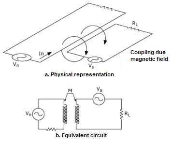
Figure 1 – Inductive Coupling – Physical Representation and Equivalent Circuit
The inductive coupling increases with:
- Frequency: the inductive reactance is directly proportional to the frequency (XL = 2πfL)
- The distance between disturbing and victim cables and the cable length which are parallel
- The cable height in relation to the reference plane (above ground)
- The load impedance of the cable or the disturbing circuit.
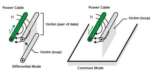
Figure 2 – Inductive Coupling between Conductors
Methods to reduce the effect of Inductive Coupling Between Cables
- Limit the cables length running in parallel
-
Increase the distance between the disturbing cable and the victim cable
-
Ground one shield end of both cables
-
Reduce the dv/dt of the disturbing cable, increasing the signal rise time, whenever possible (resistors connected in series or PTC resistors in the disturbing cable, ferrite gaskets in the disturbing and/or victim cable).
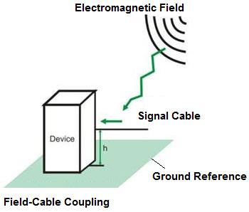
Figure 3 – Inductive Coupling between Cable and Field
Methods to reduce the effect of Inductive Coupling Between Cable and Field
- Limit the cable height (h) to the ground
-
Whenever possible place the cable near the metal surface
-
Use twisted cables
-
Use ferrite o’rings and EMI 4 filters
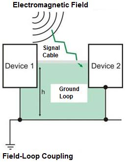
Figure 4 – Inductive Coupling between Cable and Ground Loop
Methods to reduce the effect of Inductive Coupling Between Cable and Ground Loop
- Decrease the cable height (h) and length
-
Whenever possible place the cable near the metal surface
-
Use twisted cables
-
On high frequencies ground the shield at two points (be careful) and on low frequencies at a single point
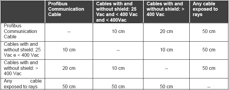
Table 1 – Minimum Distance of Separation between Cabling
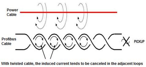
Figure 5 – Interference between Cables: magnetic fields through inductive coupling between cables and induce current transient (pickups electromagnetics)
The electromagnetic interference can be reduced:
-
Twisted cable
-
Optical insulation
-
Through the use of channels and grounded metal boxes
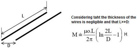
Figure 6 – Mutual Inductance between Two Conductors
To minimize the induction effect use the twisted pair cable that reduces the area (S) and decreases the induced Vb voltage effect in function of the B field, balancing the effects (average of the effects according to the distances):
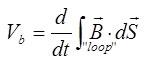
The twisted pair consists of pairs of wires. The wires are wound in a spiral in order to, through the cancelation effect, reduce noise and maintain the electrical properties of the medium constant throughout its length.
The reduction effect using the twist is efficient due to the cancellation of the flow, called the Rt (in dB):
Rt = -20 log{(1/( 2nl +1 ))*[1+2nlsen(/nλ)]} dB
Where n is the number of turns/m and l is the cable total length. See Figures 7 and 8.
The cancellation effect reduces the crosstalk between the pair of wires and decreases the level of electromagnetic /radiofrequency interference. The number of wire twists may vary in order to reduce the electrical coupling. Its construction provides a capacitive coupling between the pair conductors. It works more effectively at low frequencies (< 1 MHz). When not shielded, it has the disadvantage of the common-mode noise. For low frequencies, that is, when the cable length is smaller than 1/20 of the noise frequency wavelength, the shielding (mesh or shield) will present the same potential through its entire extension, when the shield should be connected at only one grounding point. At high frequencies, that is, when the cable length is longer than 1/20 of the noise frequency wavelength, the shielding will have high susceptibility to noise and should be grounded at both ends.
In the case of the Vnoise = 2πBAcosαinductive coupling, where B is the field and αis the angle at which the flow cuts the area vector (A) or, still, in function of the mutual inductance M: Vnoise = 2πfMI, where l is the power cable current.
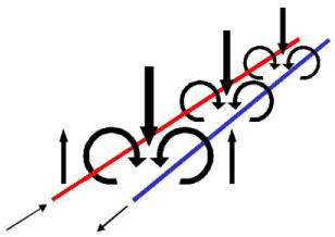
Figure 7– Inductive Coupling Effect in Parallel Cables
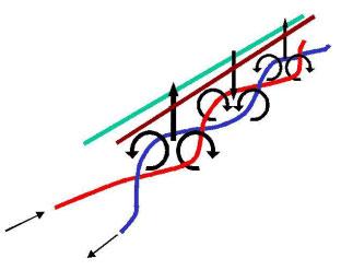
Figure 8 – Minimizing the Inductive Coupling Effect in Twisted Cables
Figure 9 – Example of Noise per Induction
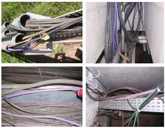
Figure 10 – Exemples of Profibus Cable Near to Power Cable
The use of twisted pair cable is very efficient provided that the induction in each twist area is approximately equal to the adjacent induction. It is efficient in differential mode, balanced circuits, and has low efficiency in low frequencies in unbalanced circuits. In high frequency circuits with multi-point grounding, the efficiency is high as the return current tends to flow by the adjacent return. However, at high frequency common-mode the cable has little efficiency.
The use of shielding in inductive coupling
Magnetic shielding can be applied in noise sources or in signal circuits to minimize the coupling effect.
To shield low-frequency magnetic fields is not so easy as to shield electrical fields. The magnetic coupling effectiveness depends on the type of material and its permeability, its thickness and the involved frequencies.
Due to its highly relative permeability, steel is more efficient than aluminum and copper at low frequencies (less than 100 KHz).
In higher frequencies, though, aluminum and copper can be used.
The loss of absorption with the use of copper and steel for two different thicknesses is shown on Figure 11.
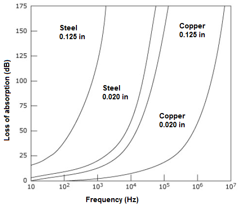
Figure 11 – Loss of Absorption with use of Copper and Steel
The magnetic shielding of these metals is inefficient in low frequencies.
Protection using metal ducts
We will see next the use of metal ducts in the minimization of Foucault currents.
The space between ducts facilitates the disturbance generated by the magnetic field. Moreover, this discontinuity may favor the difference of potential between each duct segment and if a current surge is generated, for example, by a lightning strike or a short circuit, the lack of continuity will not allow the current to flow through the aluminum duct and therefore will not protect the Profibus cable.
The ideal is to attach each segment to the largest possible contact area to provide more protection against electromagnetic induction and to have a conductor between each duct segment, with the shortest possible length, to ensure an alternate path to the currents in case of an increased resistance in the gaskets between segments.
With properly assembled aluminum ducts, when the field penetrates in the duct aluminum plate produces a magnetic flux that varies in function of the time [f = a.sen(w.t)] and produces an induced electromotive force [ E = - df/dt = a.w.cos(w.t)].
At high frequencies, the EMF induced in the aluminum plate will be stronger, resulting in a higher magnetic field that almost completely cancels the magnetic field generated by the power cable. This cancelling effect is smaller in low frequencies. In high frequencies the cancellation is more efficient.
This is the plate and metal screen effect that counters the incidence of electromagnetic waves. They generate their own fields that minimize or even nullify the field through them and act as true shielding against electromagnetic waves. They work as a Faraday cage.
Make sure the plates and coupling rings are made of the same material as the cable duct/boxes. Protect the connecting points against corrosion after the assembly, for example, with zinc paint or varnish.
Although the cables are shielded, the shielding against magnetic fields is not as efficient as it is against electric fields. At low frequencies, the twisted pair absorbs most effects of electromagnetic interference. On the other hand, at high frequencies these effects are absorbed by the cable shield. Whenever possible, connect the cable boxes to the equipotential line system.
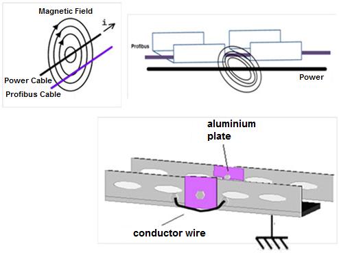
Figure 12 – Surge Protection using Metallic Channels
Conclusion
Every automation project should consider the standards that ensure adequate signs levels, such as the safety required by the application.
Annually take preventive maintenance actions and check each connection on the grounding system that must ensure the quality of each connection in relation to the robustness, reliability and low impedance, while guaranteeing that there will be no contamination and corrosion.
This article does not replace the NBR 5410, NBR 5418, IEC 61158 and IEC 61784, nor the PROFIBUS profiles and technical guides. In case of discrepancies, the norms, standards, profiles, technical guides and manufacturer manuals will prevail. Whenever possible, refer to the EN50170 for the physical regulations and safetry practices of each area.
We saw in this article several details about inductive coupling effects and how to minimize them
Bibliographic Reference
- Technical articles - César Cassiolato
- https://www.smar.com/en/system302
- https://www.smar.com/en
- https://www.smar.com/en/technical-articles
- http://www.electrical-installation.org/wiki/Coupling_mechanisms_and_counter-measures
- National Application Notes 25:Field Wiring and Noise Considerations for Analog Signals - Syed Jaffar Shah
- Aterramento, Blindagem, Ruídos e dicas de instalação (Grounding, Shielding, Noises and InstallationTips) - César Cassiolato
- O uso de Canaletas Metálicas Minimizando as Correntes de Foucault em Instalações PROFIBUS, (The use of Metal Ducts Minimizing the Foucault Currents in PROFIBUS Installations) César Cassiolato
- Ruídos e Interferências em instalações PROFIBUS, (Noises and Interferences in PROFIBUS Installations) -César Cassiolato
- https://www.smar.com/en/technical-article/tips-on-shielding-and-grounding-in-industrial-automation
- Internet research (All the illustrations, brands and products used hereby belong to their respective proprietors, as well as any other types of intellectual property.)
Reliable Solutions

