
Industrial Networks - Part 3

The specifications are continuously updated to cover every application.
Let´s examine some HART protocol details.
Simplicity: HART and the conventional current loop
Figures 32 and 33 show how to understand HART easily. On figure 32, there is na analog ent loop, where the signals from a transmitter make the passing current to vary according to the measuring process. The controloller detects the current variation through the voltage under a current sensor resistor. The loop current varies from 4 to 20 mA for frequencies below 10 Hz.
Figure 33 is based on figure 32 where the HART was added. Now both loop terminals have a modem and a reception amplifier whose high impedance does not load the current loop. The transmitter also has a power source and controller both with AC couplings. The switch in series with the power source on the HART controller in normal operation remains open. The additional components on the HART controller can be added to the current loop, as shown, or through the current sensor resistor. As regards the AC voltage, the result is the same, because the power source is a short circuit. The analog signal is not affected, since the added components are AC coupled. The reception amplifier frequently is considered as part of the modem and normally is not shown separately. On figure 33 it was drawn isolated to show how the reception voltage signal derives. The reception signal is not only AC, on the controller nor on the transmitter.
To send a message, when activating its power source the transmitter will superpose a peak topeak current signal of 1 mA on the analog signal of the output current. The Resistor R on the controller will convert this signal to voltage in the loop and this will be amplified on the receptor when reaching the controller demodulator. Similarly, to send a message to the transmitter, the controller closes its shift and connects its voltage source, which superposes a voltage of around 500 mV peak to peak through the loop. This is seen on the transmitter terminals and sent to the amplifier and the demodulator. Figure 33 implies that it is the máster that transmits as voltage source and the slave as power source.
Figure 34 shows HART signal details, whose amplitudes can very according to the impedance and capacitance for each equipment in addition to losses caused by other loop elements. The HART uses the FSK (Frequency Shift Keying), whose 1200 Hz frequency represents binary 1 and 2200 Hz frequency, binary 0. These frequencies are well above the range of frequencies of the analog signal (0 to 10Hz) so that there are no interference between them. To ensure reliable communication, the HART protocol specifies the total minimum current of 230 Ohms and maximum current of 110 Ohms, including the cable resistances.
.jpg)
Figure 32 – Conventional current loop
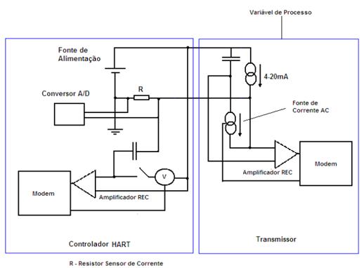
Figure 33 - HART- added current loop
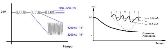
Figure 34 – HART modulation and signal
Field equipment and handhelds have an integrated FSK modem that can connect externally to a station via port serial or the USB of a PC or laptop. Figure 35 shows a typical HART field connection. Later on, will examine other types of connections.
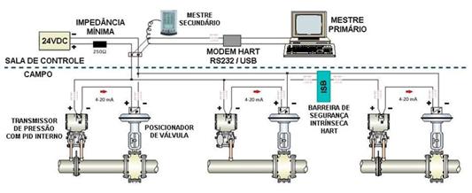
Figure 35 – Typical HART installation elements
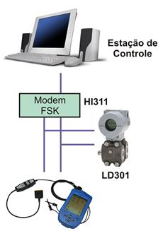
Figure 36 - HART point to point connection
A point to point connection as in figure 36 needs to configure the equipment address in zero, provided that uses the address mode in the communication to access it.
In fairly large systems, multiplexers can be used to access large numbers of HART equipament, such as that on figure 37, when the user must select the current loop to communicate via Host. In this cascade situation, the host can communicate with multiple equipment (over 1000), all of them with zero address.
There are also multidrop networks and split-range conditions. On figure 38, in the multidrop connection, note that a maximum of 15 parallel transmitters can be connected in the same line. The current passes through the 250 –Ohm resistor (hidden in the figure) will be high and cause a high voltage drop.
Therefore, make sure that power source voltage is adequate to supply the minimum operational voltage.
In multidrop mode the current remains in 4mA, useful only to power the loop equipment.
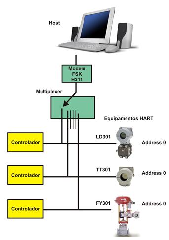
Figure 37 – HART connection via multiplexer
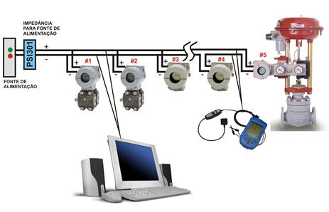
Figure 38 – HART connection in Multidrop
The split-range condition is used in special situations when normally two valve positioners receive the same control signal, such as, one to operate in 4 to 12 mA and the other in 12 to 20 nominal current. In this condition, the positioners are connected in series on the current loop with different addresses and the host will identify them via communication. See figure 39.
.jpg)
Figure 39 – HART connection via Split Range
As seen before, the HART uses the 4-20mA signal superposing a FSK technique signal, and switching by frequency shift keying, whose 1200 Hz frequency represents binary Zero. Each individual byte on the layer 2 telegram is transmitted in 11 bits, using 1200 Hz.
Cabling
A twisted pair of cable should be used where total resistance is required, as this collaborates with the total load, attenuating the signal and its distortion. In long lines affected by interferences, the shielded cable is recommended and grounded on the same spot, preferably at the power source negative.
Layer 2
HART protocol operates according to the Máster-Slave pattern, when the slave will only transmits a message under the master´s request. Figure 40 shows how simple is the exchange of data between the master and the slave. The master starts every communication and the slave only responds if requested. There is a perfect time control between the commands sent by the master and also between masters, when there are two of them in the bus.
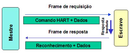
Figure 40 – HART frame
The coexistence of several protocols in the same plant
From now on the coexistence among multiple protocols is expected to become usual, mainly on large facilities whose investments should be preserved. Figure 41 is a typical example of a system with the Foundation Fieldbus and HART protocols coexisting in the same plant. In this case, a HART-FF interface, the HI302, is used, allowing point to point and multidrop connections. The HI302 is a bridge between HART equipment and FF systems, having 8 HART master channels that allows the user to execute maintenance, calibration and monitor the sensor status, general equipment status, among other information.
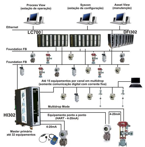
Figure 41 – Integration Foundation Fieldbus and HART using the HI302
Reliable Solutions

