
Relays x Sensors

INTRODUCTION
The progress of Physics and Electronics in recent years has been remarkable. Their development was certainly the most striking among the many technical areas, to the extent that today we cannot live without the facilities and benefits provided by them in our daily tasks. And the same applies to processes and industrial control, where we have witnessed the advancement of micro-processers, electronic components, the Fieldbus technology, the use of Internet, etc.
This article will focus on two important components on automation and process control and manufacture: Relays and Sensors. Both elements are widely used, with countless functionalities and resources. The first, with striking features for execution, and the second, with quantitative and qualifying characteristics on measuring, performance and diagnostics in general.
RELAYS
A relay, in simple words, is a switch activated electronically in an electric circuit to interrupt or not the electric current according to a control circuit.
When the control circuit is powered, the relay shuts and allows the current flow between two connected points. When the control command is turned off the circuit opens.
Most relays use an interesting gadget, whose electrical current that flows through the circuit is deviated to feed back the control circuit, which is opened and kept until another external action interrupts the current. These devices are called bistable, as they oscillate between two statuses that are not altered on their own and an external action is needed to modify them.
For better understanding, let us analyze the most common relays, which are electromechanical devices (see figure 2), whose coil is wound around an iron nucleus forming an electromagnet. Near the electromagnet is installed a mobile armature that opens and shuts the contacts. When an electric current crosses the coil a magnetic field is formed over the armature that attracts it and activates the contacts.
.jpg)
Figure 1 – Relay symbol
.jpg)
Armature
3 and 4: Contact terminals
Coil
1 and 2: Coil terminals
Figure 2 – Relay scheme
A control current applied to the relay coil makes possible to open, close or commute the contacts and controls the currents that circulate through external loads. When the current stops circulating on the relay coil, the magnetic field created disappears and the armor goes back to its natural position with the spring action.
The most simple application of a simple contact relay is on the on/off control to turn off a load, for example, to control a pump, turning it on or off, according to the tank level. Note the symbol used to represent this component on figure 1. Relays can have normally open, normally shut and mixed contacts.
But also there are electronic relays made up of transistors connected so ingeniously that it takes only one electric potential applied to the control terminal to shut the circuit. In addition, there are solid state relays, whose details will be shown next.
- Nominal voltage, operation voltage and maximum work voltage.
- Nominal current.
- Ohm resistance.
- Dissipated nominal power.
- Contact features: the contact surface; the maximum voltage and current admitted and controlled by the circuits; contact resistance and materials (copper, silver and tungsten); the number of contacts and their disposition will depend on the relay applications; capacitance between contacts, etc.
- Time spent by the relay to shut or open its contacts.
- Load time: AC or DC. Note that the opening time increases in inductive load applications.
- Mechanical lifespan.
- Etc.
The current that activates the relay is called activation current. This current is necessary to create a magnetic field intensity that attracts an armature closer to the coil. Once this inertia is exceeded, the magnetic field does not need to be so intense to keep it near the coil. The current that keeps the relay shut is called maintenance current. The current that will circulate in its coil is a function of the winding resistance, which is calculated by the Ohm law, as well as the power that will be dissipated in it.
The use of relays requires some practical care during their deactivation (removal of the command control), due to the polarity voltage opposed to that which created the magnetic field and whose cost is high because of the inductor typical abrupt variations. This cost is related to the variation rate di/dt and the inductance (L) of the coil (V=Ldi/dt). If the relay activation control circuit is not protected the result will be bad performance or total damage. The most common technique is the reverse diode or the varistor parallel to the relay coil.
In the diode case, when the current is interrupted, a high voltage induction occurs on the coil and the diode gets polarized in a direct sense, serving as pathway to the current, thereby protecting the firing circuit. The varistor or VDR uses its characteristic that its resistance significantly reduces when the voltage limit applied is exceeded. This property is used when the relay is deactivated and when the current could damage the firing components. The varistor voltage must be specified with a value greater than the relay firing voltage, though smaller than the maximum voltage supported by the component used in the firing.
Another important detail in the automation and control area is the type of mounting and the area classification requirements. There are open relays and closed ones wrapped with the most different materials and sealing compliant with hazardous areas and subject to the most varied environments.
Mind you that the relay is a connection element and normally will be related to the final control elements, where care is required not only for specification but operationally as well.
SOLID STATE RELAYS
This class of relays is developed with electronic devices and components based on semi-conductors that allow the control and flow of electrons, according to the changes on the power level, modifying the input voltage levels to obtain rectification, amplification and switching characteristics. Some of these features are highlighted below:
- long operational life;
- severe conditions environments (dirt, humidity, combustion, etc.);
- silent operations;
- high speed switching;
- low firing consumption;
- compatible with applications that involve digital logic based on micro-processors and controls in general;
- low susceptibility to electromagnetic interference;
- high operation number;
- optical isolation;
- protection circuits (snubbers);
- phase angle, pulse train or on-off working mode;
- etc.
Its application field is wide, including from integration compatibility with micro-processors, TTL and MOS logic systems to AC and DC load action and control, like motors and solenoids.
SENSORS
Undoubtedly the use of sensors on industrial applications is something very extensive and impossible to cover in a single article. The idea here is to present a general aspect of some concepts involving sensors.
Sensors will be treated as input transducers in this article, although in practice the word sensor and transducer wind up being used as synonyms. For clarification, the transducer is a device that “takes” energy from a measurement system and converts it to an output signal that can be translated into an electric signal corresponding to the measured value. On the other hand, the sensor suggests something beyond our physical perceptions and involves exactness, response time, linearity, hysteresis, dead zone, etc.
When speaking of sensors, it is important to bear in mind that some information electric dominions may be related to them, such as:
- analog dominion, for signal amplitude (current, voltage, power);
- time dominion, for time relations (period or frequency, pulse width, phase);
- digital dominion, whose information characteristic is binary and can be conducted by a pulse train or by a serial or parallel code, for example.
There are also non-electric dominions, including chemical ones.
Due to the wide variety of sensors, normally they are classified according to a few criteria:
- Power Supply: according to this criterion, they are classified as active sensors, whose power supply derives from a secondary source, or passive sensors, which do not consume energy and the output power comes from the input. Examples are the thermistor (active) and the thermopar (passive).
- Output: they are classified as analog and digital, as the potentiometer and the encoder, respectively.
- Mode of operation: according to their function, they are classified in deflection or null mode. On the first case, the measured value generates a physical effect action contrary to the variable being measured, as on a servo-accelerometer. Normally, the null mode is more exact as it enables calibrating the contrary effect with high-exactness references, however slow.
- Input-output: they are classified according to the input-output ratio in sensors of first, second, third or greater order. The order is related with numbers of independent elements that store energy and affects the exactness and response time, important factors when these sensors are part of control loops.
There is a wide variety of sensor and their applications are countless in automation, industrial control and manufacture: temperature, pressure, density, flow, humidity, position, speed, acceleration, force, torque, displacement, color, etc.
Sensors are varied: inductive, capacitative, optical, ultra-sound, etc.
FEATURES THAT SHOULD BE CONSIDERED IN SENSORS
In practice, what is expected from a sensor is that its sensitivity should be based only on the magnitude to be measured and that the output be only an input function. However, no measurement is got under ideal circumstances and that any sensor suffers some type of interference and internal disturbances, such as temperature effects, static pressure effects, magnetic interference effects, etc.
Another factor to be taken into consideration is the static behavior that affects directly the performance of a sensor, involving exactness, precision, sensitivity, linearity, resolution, random, systematic and dynamic errors, speed response, input impedance, etc.
With the technological advancement, multiple compensation techniques were developed and are employed today to minimize these effects on acceptable and reliable levels.
RELAY & INTEGRATED SENSORS
The technological progress and chiefly the development of field networks and the distribution of intelligence on the field, today the market presents relays and sensors integrated on the same equipment with reduction of installation costs, increase of field buses addressing (as only one device, even having one or more sensors and one or more relays, represents a single network node), thereby increasing the flexibility of applications, facilitating integrations, etc.
Simple devices as temperature supervision relays may exist that for application on the evaluation of temperature in solid, liquid or gaseous means (for motor protection, monitoring in general involving temperature on industrial processes, etc.), whose temperature is captured by the sensor, evaluated by the relay and monitored within pre-configured limits. The output relay is turned on or off on the value of reference, depending on the adjustments on the device parameters. There may be relays via PC communication or via Profibus DP, Asi, Foundation Fieldbus/Modbus, with diagnostics capability, for electronic protection and control of motors, and so on. Other families focused on safety as the flame-detecting relay, which uses ionization or photo-resistor sensors.
USE OF SENSORS AND RELAYS ON FIELDBUS
This article will present now some details on what is new in terms of the development of Foundation Fieldbus technology for discrete activation via solid state relay in small and medium-size applications with equipment directly connected to the bus, namely the FRI302- Fieldbus Relay.
The FRI302 is an equipment for micro-processed industrial control developed specifically for the logic control of discrete variables, which, having a large library of Foundation Fieldbus functional blocks can be used in all types of control. Smar was the first world company to introduce to the market an equipment directly connected to the fieldbus bus that enables discrete activation via solid state relays.
This development feature is due mostly to the technological innovations of micro-processers and micro-controllers.
The FRI302 easily integrates Fieldbus and the conventional discrete outputs. Discrete devices such as on-off valves, pumps, electrical conveyors and actuators, speed variators, etc. may be integrated to the Foundation™system via H1 bus, using the FT302. It can be distributed on the field with conventional discrete devices without the need of wiring between them and the control room. The FRI302 allows that discrete and analog inputs and outputs be easily available to the configuration of control strategies using the Foundation™ Function Blocks concept, turning the system homogeneous enough to make these devices look like simple diapositives on a fieldbus bus. It has several function blocks like PID, PID STEP, ARITH, AALM, ISEL,TIMER, FFET, DO, MDO, etc.
Figure 3 shows the FRI302 functional diagram and figure 4 shows the output physical connections.
.jpg)
Figure 3 – FR302 functional diagram
Features
° 3 output options:
2 solid state relays contacts normally closed (NF),
2 solid state relays contacts normally open (NA),
1 NF and 1 NO
° Output: 2 solid state relays contacts:
NA: Maximum switching voltage: 400 Vpeak
AC Maximum switching current: 150 mA
DC Maximum switching current: 250 mA
NF: Maximum switching voltage: 350 Vpeak
AC Maximum switching current: 100 mA
DC Maximum switching current:165 mA
- Backup master functionality
- Simple and Advanced Function Blocks with instantiation
- Easy firmware update
- Data saving during shutdown
- Power supply: Via H1: 9-32Vdc
Quiescent current consumption: 17 mA
H1 POWER SUPPLY TERMINALS
COMMUNICATION TERMINALS
GROUND TERMINALS
OUTPUT 2
OUTPUT 1
.jpg)
Figure 4 - Output Physical Connection
.jpg)
Figure 5 – Physical Connection with DOs
Physical Connection with DO Function Blocks
Through two Digital Output (DO) function blocks it is possible to command two DC or AC loads.
Physical Connection with PID_STEP Function Block
Through a PID STEP function block it is possible to get an interesting application with electric actuators.
Any electric actuator, including the SMAR AD/AR/AL series, turns into a Fieldbus Actuator, which makes the FRI302 the ideal equipment for plant updates and instrumentation.
The PID Step block is the best indication for theses cases to modulate the valve without needing feedback.
.jpg)
Figure 6 – Physical Connection with the PID STEP
Example of Level Control Application
Let us suppose that a fieldbus network has a level control whose FRI302 level transmitter is measuring the level of a tank. The level signal is provided via the Analog Input block (AI) to an Analog Alarm block (AALM) instantiated on the FRI302. When a pre-configured level value is reached through a discrete output (DO) block, the pump that powers the tank can be turned off and also turn it on as soon as the level becomes lower than the configuration limit. See figure 7.
.jpg)
Figure 7 – FR302 application on level control.
Next follows details of a capacitive pressure sensor used on SMAR pressure transmitter series, including the FRI302, mentioned on the Relay Fieldbus application.
The pressure sensor used by SMAR pressure transmitters has a capacitive cell, shown on the Figure 8 scheme.
Sensor Diaphragm when P1= P2
.jpg)
CH and CL capacitors fixed plates
Figure 8 – Capacitive Sensor
Where:
P1 and P2 are pressures applied on the H and L chambers.
CH = capacitance measured between the fixed plate on the P1 side and the sensor diaphragm.
CL = capacitance measured between the fixed plate on the P2 side and the sensor diaphragm.
d = deflection suffered by the sensor diaphragm
= deflection suffered by the sensor diaphragm due to the application of the differential pressure DP = P1 - P2.
It is known that the capacitance of a capacitor with flat and parallel plates may be expressed in function of the plates area (A) and the distance (d) that separate them as:
.jpg)
Where,
= dielectric constant of the existing mean between the capacitor plates.
If we consider CH and CL as same-area, parallel flat plate capacitances when P1 > O2, we have:
.jpg)
On the other hand, if the differential pressure (DP) applied to the capacitive cell does not deflect the sensor diaphragm beyond d/4, we can admit .jpg) proportional to
proportional to  , namely:
If developing the expression (CL-CH) / (CL+CH), we will have:
Since the distance (d) between the CH and CL fixed plates is constant, we notice that the expression (CL-CH) / (CL+CH) is proportional to .jpg) and also to the differential pressure to be measured.
and also to the differential pressure to be measured.
So, the capacitive cell is a pressure sensor made up by two capacitors of variable capacitances, according to the differential pressure applied.
These capacitors are part of an oscillation circuit whose frequency depends on the differential pressure applied. This frequency is measured by the CPU of the pressure transmitter high resolution, high exactness and process speed, being inversely proportional to the applied pressure.
Figure 9 shows a diagram of the LD302 hardware and figure 10, the several sensor models for different applications.
.jpg)
Figure 9 – LD302 hardware diagram
Differential: DP = PH – PL
Vacuum
Filling fluid
Absolute: DP = PH – 0
Level: DP = PH – PL
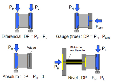
Figure 10 – Sensor Models
CONCLUSION
This article showed the importance of relays and sensors, combined with the advancement of micro-processers, in automation and process control, in addition to details of a micro-processed equipment for discrete activation and an example of capacitive pressure sensor.
REFERENCES:
(Se for preferível tradução)
- FRI302 and LD302 Operation Manuals
- https://www.smar.com/en
- Technical articles, César Cassiolato
- Saber Eletrônica Edition 449, Relays x Sensors - César Cassiolato and Edson de Oliveira Emboaba
- Control & Instrumentation Edition 92, Relays x Sensors, César Cassiolato and Edson de Oliveira Emboaba
Reliable Solutions

