
Tips for trouble shooting on the PROFIBUS-DP

|

Introduction
Although very simple and the most used PROFIBUS-DP physical medium technology, the RS485 still meet some field situations that could be prevent and reduce the commissioning and startup time and avoid undesired intermittences and shutoffs during the operation.
More situations will be detailed in a further article. Watch the SMAR web site: https://www.smar.com/en
Attention
Whenever possible, refer to the EN50170 for physical regulations as well as for safety practices on each area.
Be careful and attentive with safety in measurements, avoiding contacts between terminals and the wiring, as the high voltage may cause electrical shock. Remember that each plant and system have their own safety procedures. Get to know these details before starting to work!
In order to minimize the risk of possible safety problems, follow the applicable standards for safety and classified areas that regulate the installation and operation of equipment. They vary according to the area and are constantly being updated. The user must determine which standards to follow and make sure that each equipment must be complied with them.
Inadequate installations or the use of an equipment for the wrong application can harm the performance of a system and its process, besides being a source of danger and accidents.
The RS485 physical medium
This standard has two independent channels known as A and B, which transmit similar voltage levels however with opposite polarities (VOA and VOB or, simply VA and VB).
For this reason, it is important that the network is connected with the correct polarity.
Though opposite ones, one signal is not is the return of the other, that is, there is no current loop.
Each signal returns through the ground or a third returning conductor, however the signal should be read by the receptor in a differential way, without connection to the ground or the return conductor.
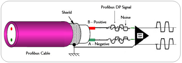
The grounding of this communication system is the great advantage of the differential signal: note on figure 1a that the signal is transiting with inverted phases on the conductors of the cable, while the noise transits with the same phase.
On the input terminals of the differential amplifier, the PROFIBUS communication signal arrives in differential mode and the noise in common mode, being rejected. Hence, all the noise induced into the cable, generally of electro-magnetic origin, will be mostly rejected.
Figure 1a – RS485 PROFIBUS-DP Signal
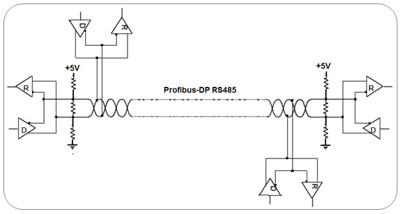
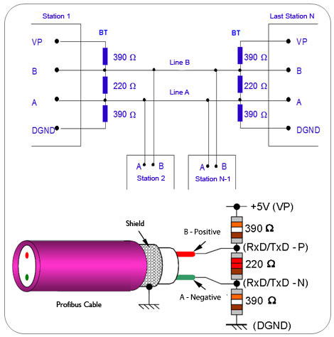
Figure 1b – RS485 PROFIBUS-DP NetworkDifferential transmission lines use as information only the existing potential difference between the two twisted-pair conductors, regardless of their potential difference in relation to the voltage referential (common ou ground)
- The RS-485 uses an unbalanced differential pair, meaning that each device on the network must be connected to grounding and provide a return signal to minimize the noise on the data lines. The cable must be shielded twisted pair type and whenever necessary transient protectors should be used.
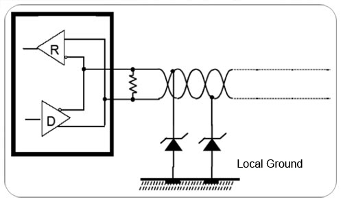
Figure 1c – RS485 PROFIBUS-DEP network with transient protector
- Termination: In this regard, many conceptual errors have been noticed in practice. The terminator is the impedance added to the PROFIBUS network with the purpose of harmonizing the network impedance. The longer the network length, the more powerful may be the signal distortion. The terminator eliminates communication errors caused by distorted signals. It is worth mentioning that if the terminator is not installed, the wiring works as an antenna, which favors the signal distortion and increases the sensitivity to noises. The typical impedance is the load value that placed on the end of this line does not reflect any energy. In other words, it is the load value that provides a zero coefficient of reflection, or, still, a relationship of stationary waves equal to one.
Table 1 shows how to check the PROFIBUS-DP network in relation to terminators and also to the cable by using a multimeter.

8 (A)
3 (B)
Cable ok
Short between A and B
1 active BT
- 2 active BTs
- << 110 Ω, more than 2Active BTs
8 (A)
shield
Cable ok
Short between A and shield
----
----
3(B)
shield
Cable ok
Short between B and shield
----
----
Table1 shows how to check the PROFIBUS-DP network terminators and cable with the use of a multimeter.
- Lines A and B on PROFIBUS-DP cable: on the field it is usual to find these two lines inverted on the connectors. On PROFIBUS-DP the rule is:
a. Line B: Signal positive – Red color (Pin 3 of DB9)
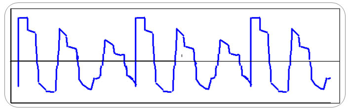
b. Line A: Signal negative – Green color (Pin8 of DB9)Figure 2 shows the PROFIBUS-DP signal with inverted A and B lines at 200m from measuring point.
Figure 2 – PROFIBUS-DP signal with inverted A and B lines at 200m from measuring point (Courtesy by Rafaela Castelhano de Souza).This situation can be identified with the network deactivated and a voltmeter. If Line B is not more positive than Line A, there is a problem in these connections.
- Tristate and Idle condition (1.0 V): This condition occurs when no PROFIBUS equipment is working and the circuits go into a high impedance state. The Lines A and B resistors are adjusted for the data line not to float and this generates a BIAS DC current:
- a) Resistors with high values: decrease the immunity to noises and generate instability on the network.
- b) Resistor with low values: overload the communication drivers.
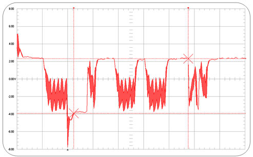
Figure 3 – PROFIBUS-DP bus terminator
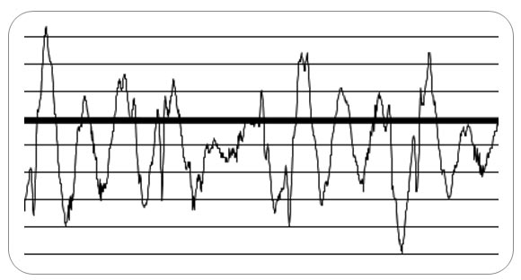
Figure 4 – PROFIBUS-DP signal with overload problema on 485 drivers
- Data collision: This is the case when there is no equipment supplying data for the PROBISU network, no alteration on the signals that change the bit time, or even the idle time. We must observe on the signals if any equipment is requiring data faster than one byte. The collision occurs when the equipment attempts to communicate and the line is not on tristate condition. Another situation is when there are repeated addresses on the bus. Since the default address is the 126, is common finding in some situations the repeated address condition, mainly during commissioning and startup applications.
Figure 5 exemplifies what happens on the bus in this situation.
Figure 5 – Deformation on the RS485 signal with equipment that respond to the master for having the same address.This article does not substitute the IEC 61158 and IEC 61784 standards nor the PROFIBUS profiles and technical manuals. In case of discrepancy or doubt, these standards, profiles, technical literature and manufacturer manuals prevail. Whenever possible, consult the EN50170 for physical regulations, as well as the safety practices for each area.
For further details see the articles:
- “Sinal Diferencial RS485 – PROFIBUS DP” em http://www.profibus.org.br/detalhe_noticia.php?id=37
- ‘”Transient protectors in PROFIBUS networks” em https://www.smar.com/en/technical-article/transient-protectors-in-profibus-networks
See more information on PROFIBUS technology.
For details on a truly open, network-based, automation system, consult SYSTEM302
References:
- Manuais SMAR PROFIBUS
- Grounding, Shielding, Noise and installation tips - César Cassiolato
- EMI – Interferência Eletromagnética - César Cassiolato
- https://www.smar.com/en
- Training material and technical articles PROFIBUS - César Cassiolato
- Technical Specifications and Installation Guides PROFIBUS.
- https://www.smar.com/en/technical-articles
* César Cassiolato was a Certified Engineer in PROFIBUS Technology and PROFIBUS Installations by the Metropolitan University of Manchester, United Kingdom.
Reliable Solutions

